(Note this is a work in progress project and page: last update July 09th 2023)
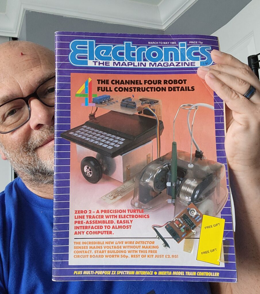
I first became aware of the Zero 2 robot back in 1985 as a result of the Maplin Magazine article (and advertisements in Your Sinclair and other magazines at the time). This particularly inexpensive and accessible robot dropped to the back of my mind until I came across David Buckley’s website by accident, when looking for Sinclair QL software. This sparked my interest to build a clone of the robot and open-source the design files. Subsequent conversations led to me getting hold of some original parts from David to allow a build of the original robot.

Clone Robot Main Board Design
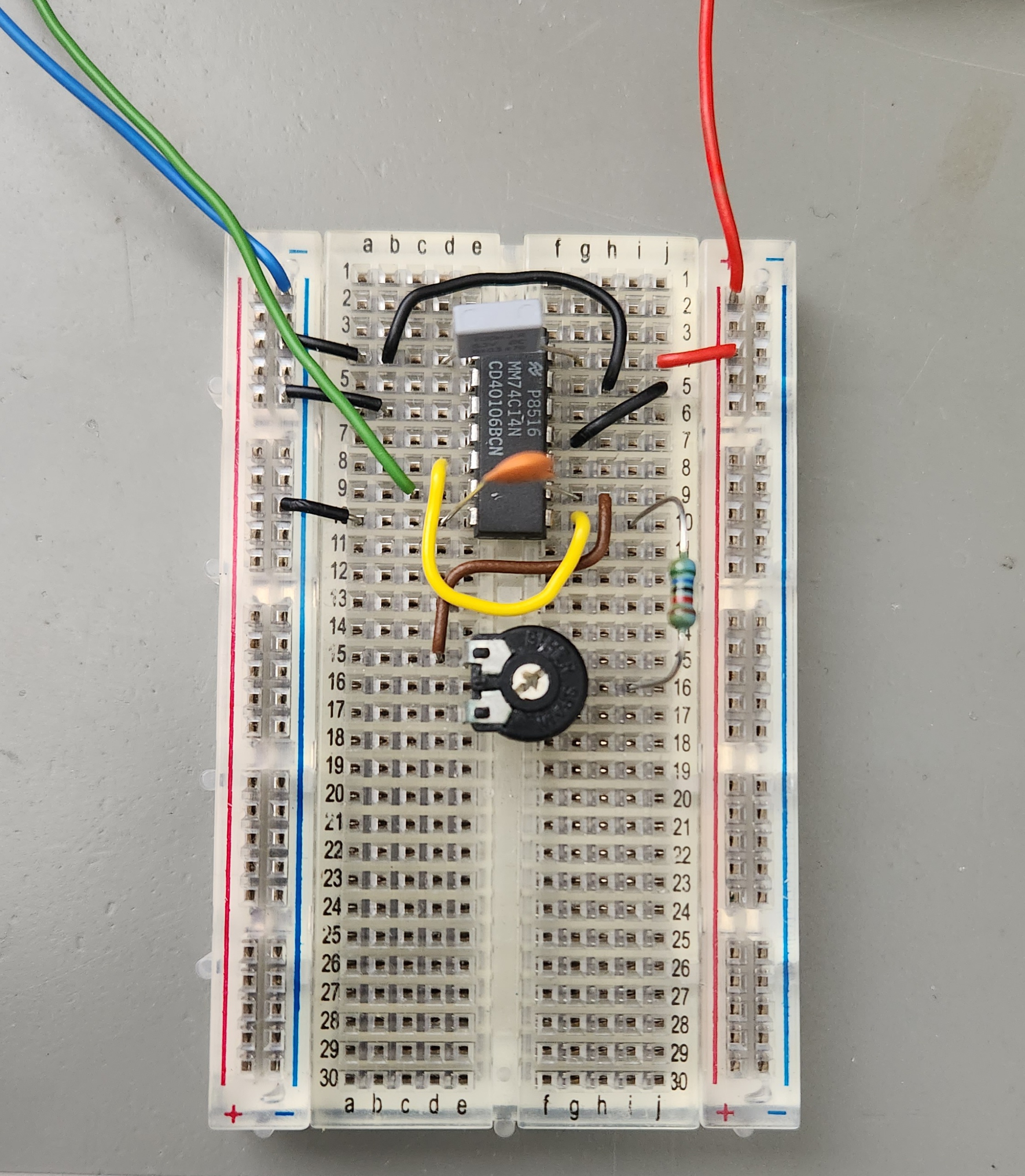
The first step was to get hold of some good quality images of the PCB from David. He also gave me numerous notes on errors or improvements which he never got a chance to make to the original boards. Of particular note is the clock generator which was a strange arrangement by the original hardware designer. This was replaced by a single RC oscillator using the original CMOS Schmitt trigger inverter, but this time with the addition of a 4K7 pot to allow calibration of the clock to account for variations (mostly in the capacitor). Here’s the prototype clock being checked. The serial interface is designed to run at 4800 baud, and the UART has a /16 divider meaning the base clock frequency should be 76.8kHz. According to David the serial interface is actually quite tolerant to inaccuracies.
The design itself is quite interesting. I previously came across the 6402 UART in Robert Penfold’s 1988 book Musical Applications of the Atari ST’s where he uses it as a MIDI to CV/Gate converter to interface to analog synthesizers.
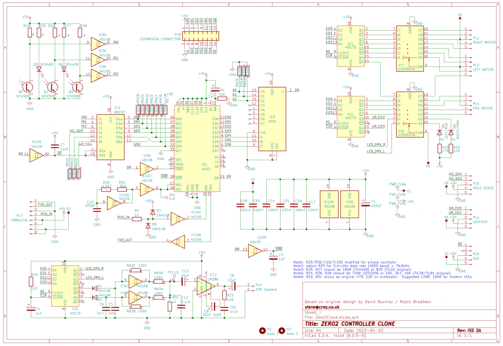
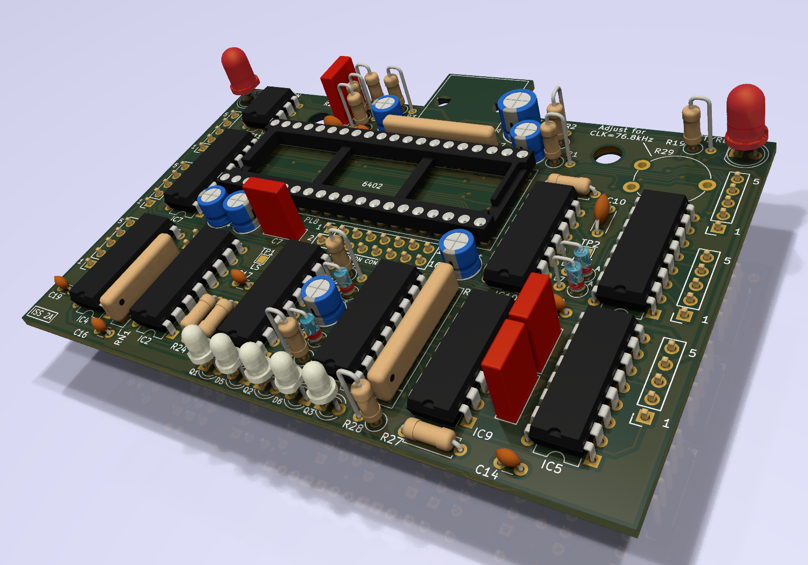
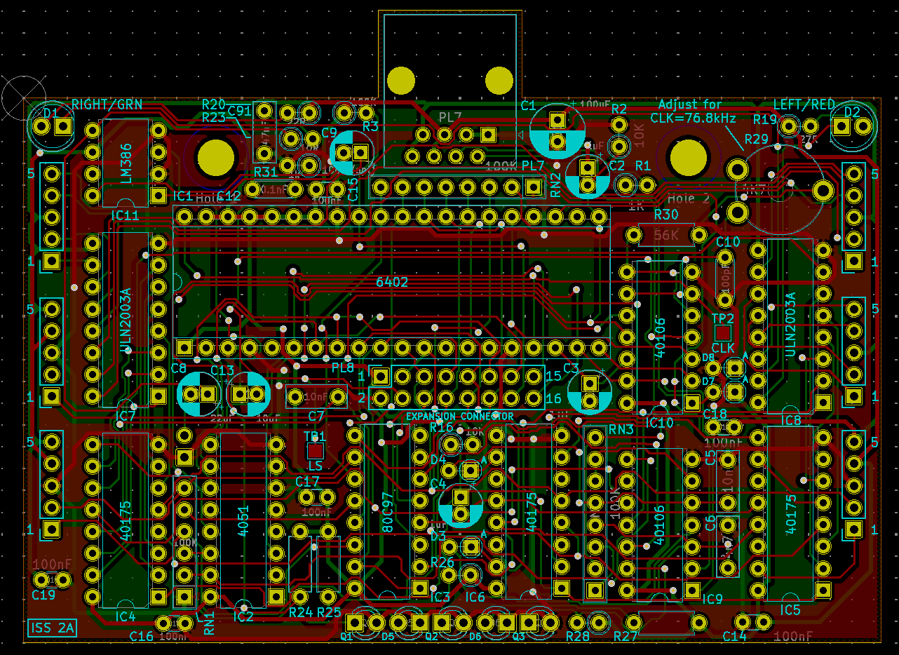
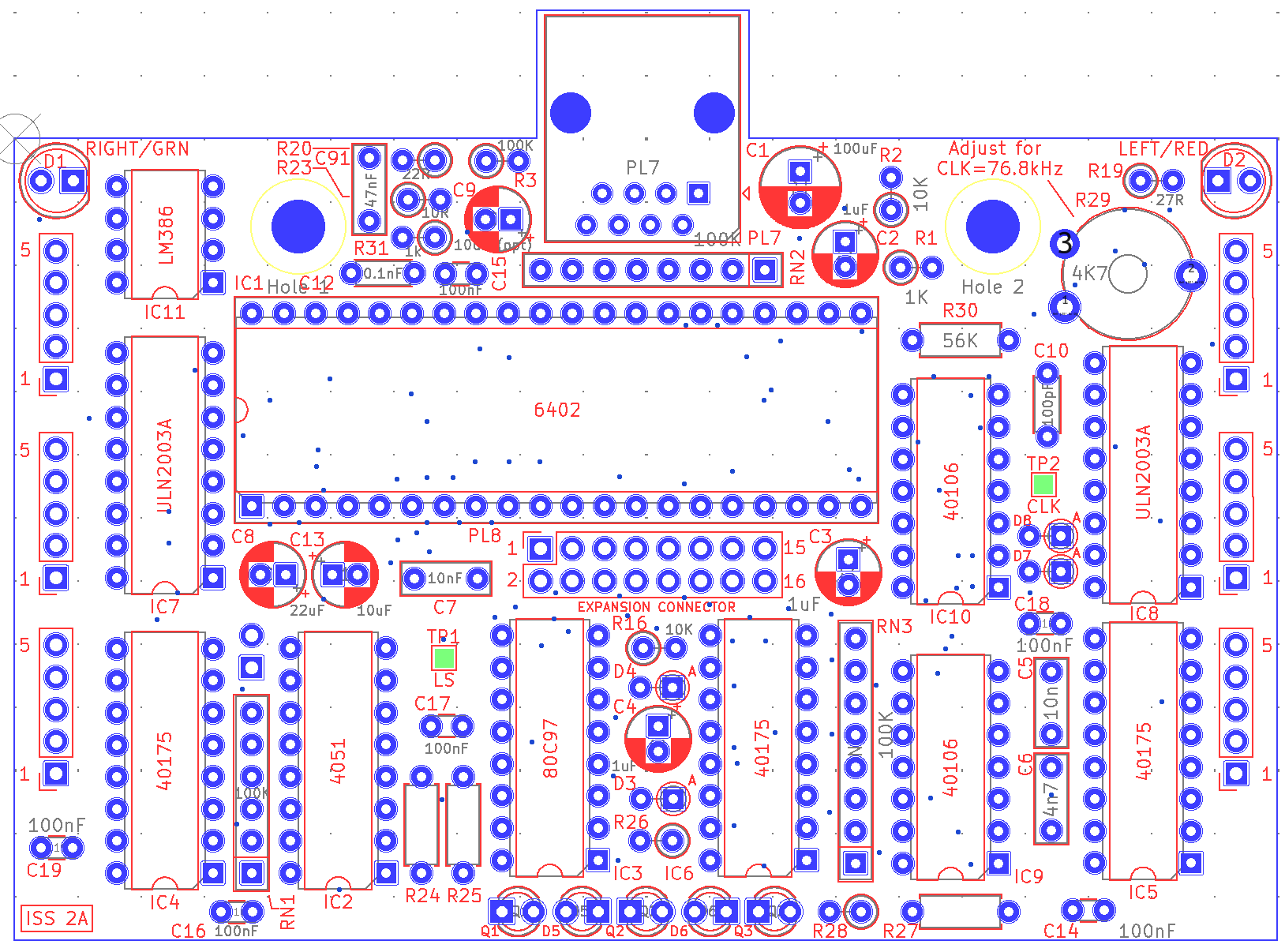
Anyway, here’s the prototype schematic (redrawn to be much easier to read than the original), the prototype PCB and some 3d views. Note that the expansion connector is actually fitted to the front side of the PCB (not the back as shown in the 3d views). To be compatible with the original it should use a female footprint on the topside but with a male connector (I might re-draw a custom footprint for a future update). Github repo with the design files coming soon !
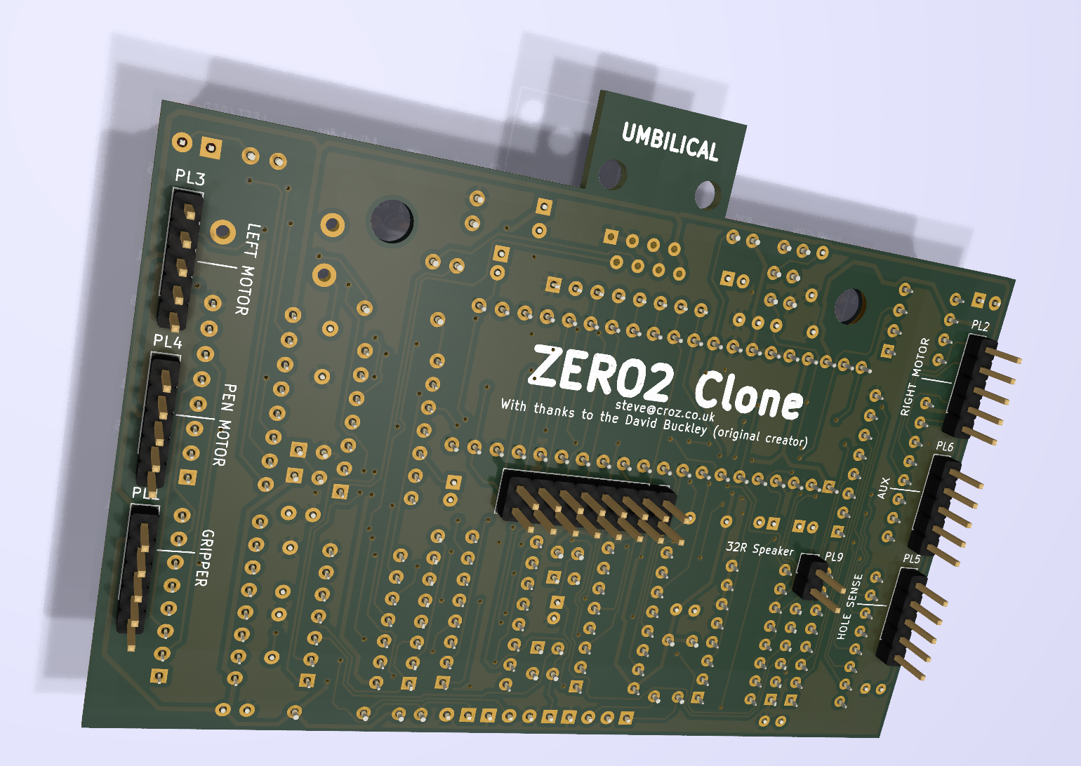
Since the original BT-style phone connectors are ‘unobtanium’ (at least in the US), I took the liberty of replacing this with an RJ45 connector. This allows a standard off-the-shelf network cable to be used to connect the robot to the interface (more on that later) but does require the bodyshell connector hole (if you happen to have an original) to be enlarged.
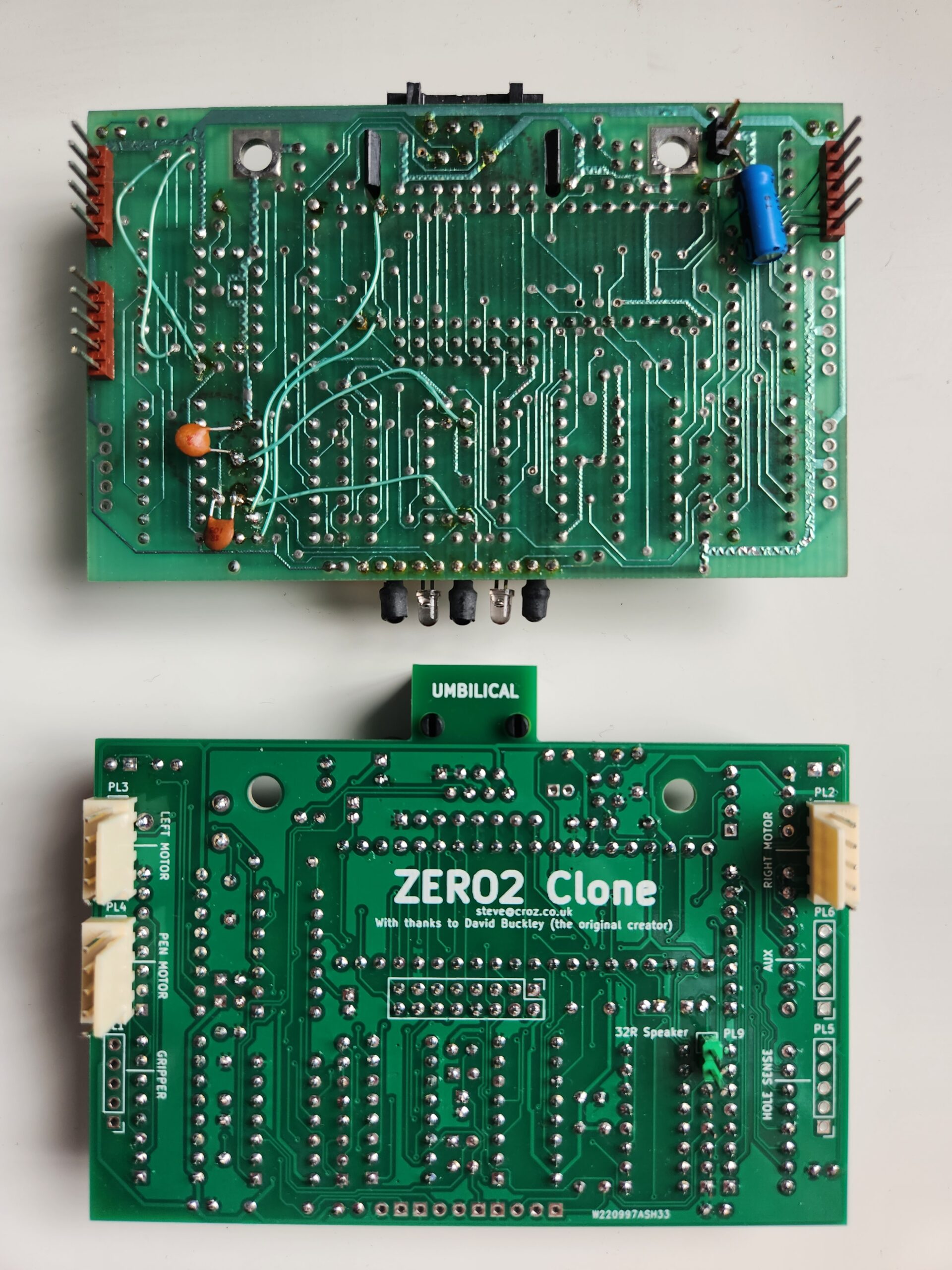
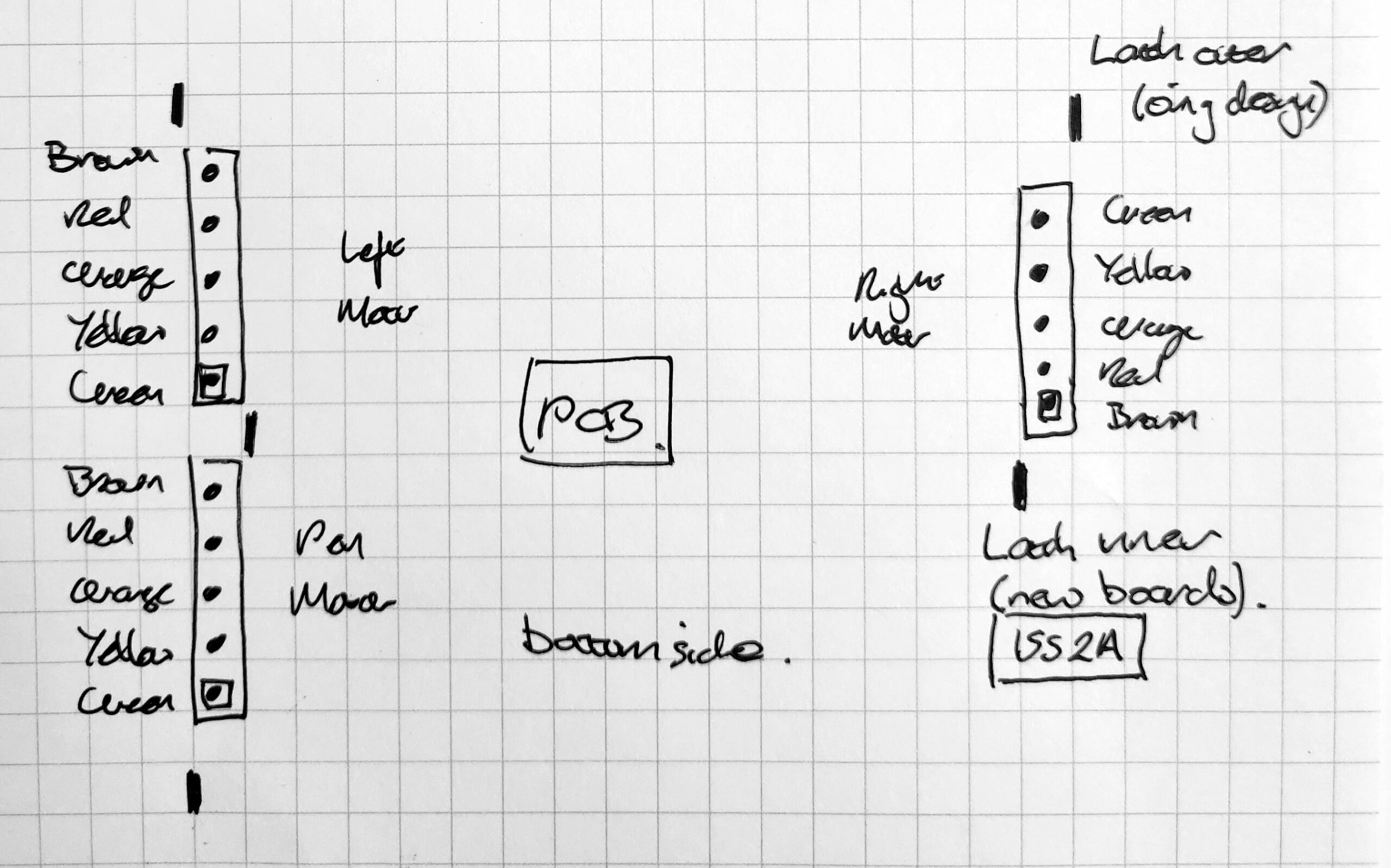
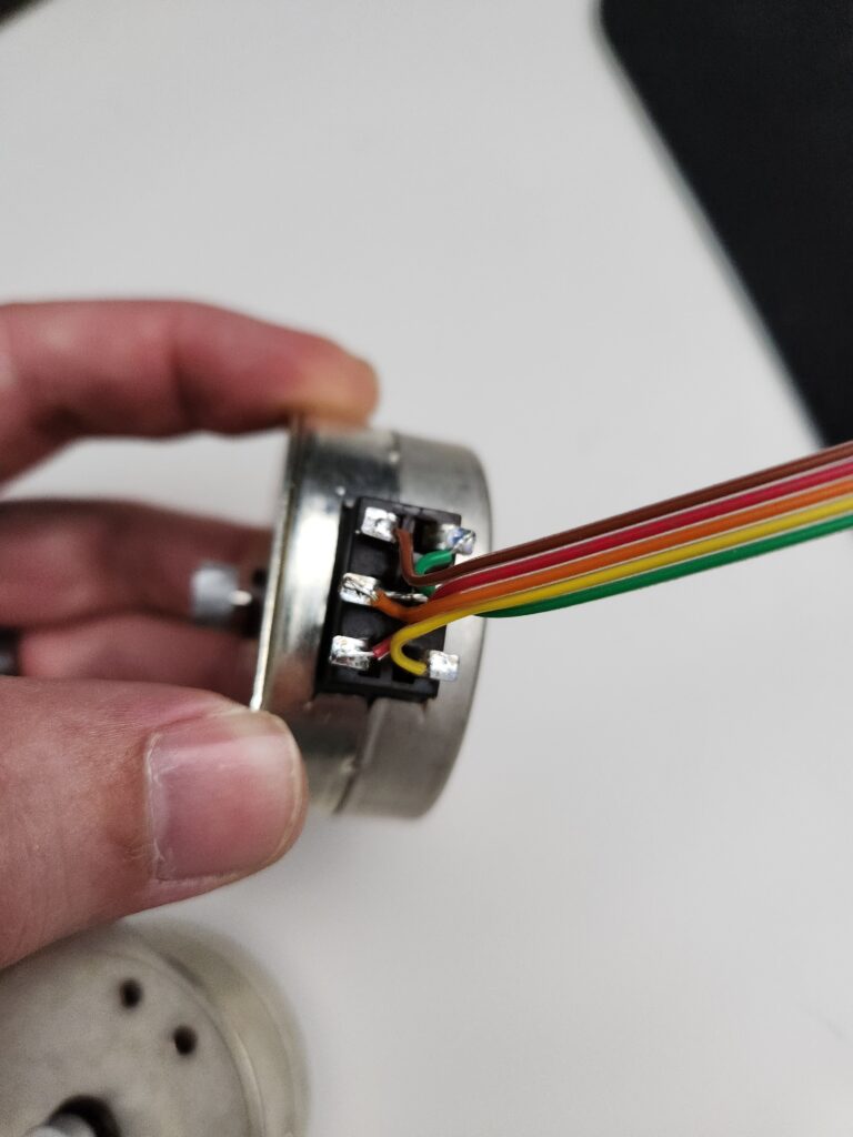
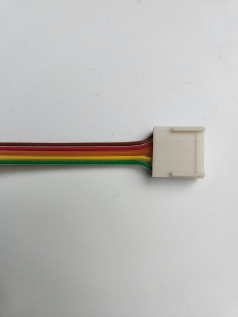
Here’s how the original and new PCBs look both unpopulated and (mostly) populated). You may notice that the original PCB shown here has unpolarized/non-latching connectors but the new one has latching connectors. The initial ISS 2A of the board has an ‘opportunity for improvement’ to move the connector footprints slightly outward to allow the connector latches to be mounted to the outside of the board (as originally intended). Note therefore that the connector wiring is reversed on this issue board and the motor wiring (below) shows opportunity for the latches to be to the outer or inner orientation.
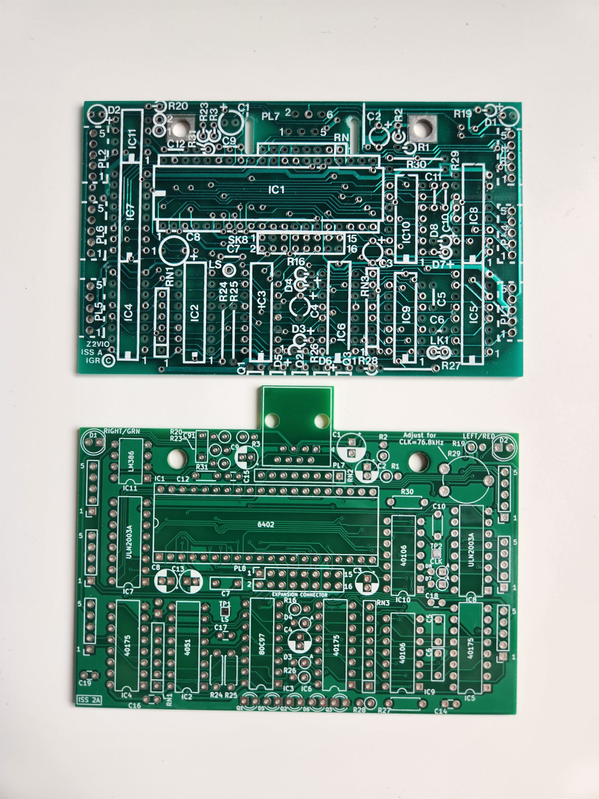
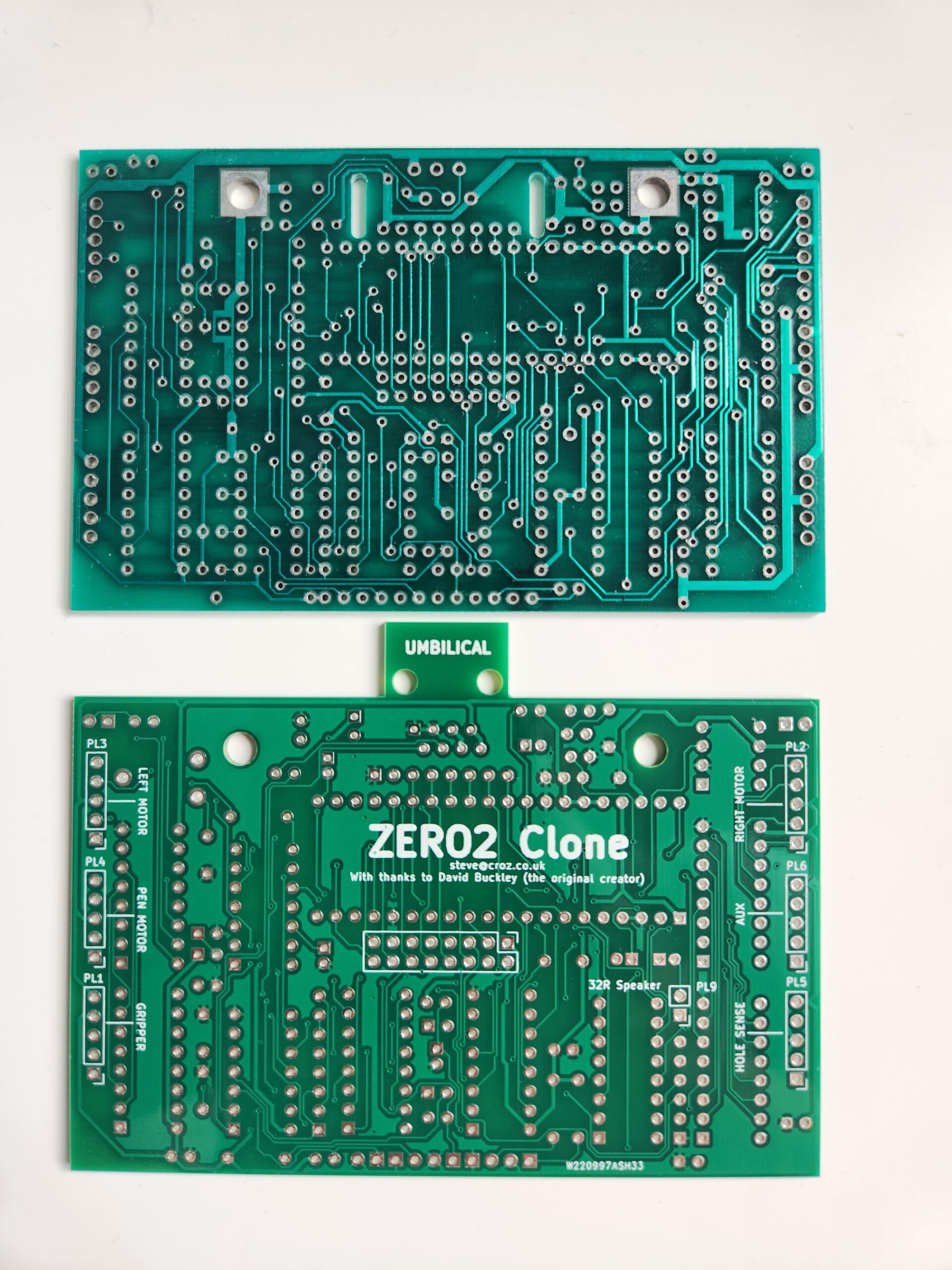
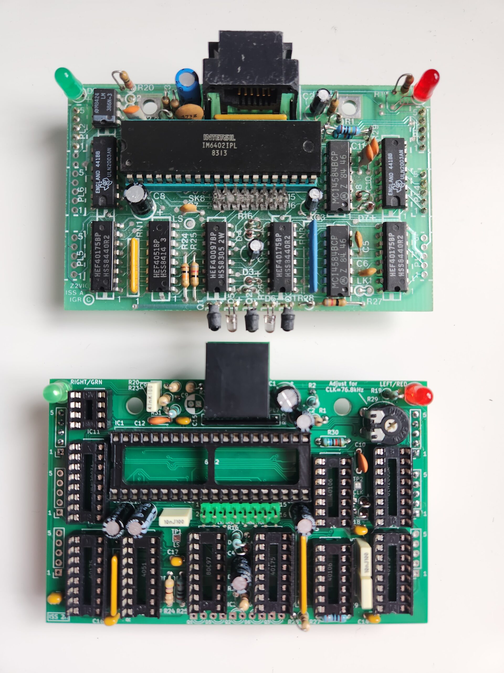
Note that the original boards had many ‘bodge wires’ – hopefully none on the new boards, but we need to test first. Note also that my prototype has rather tall capacitors. I plan to replace these with low-profile parts to allow development of a daughter board that plugs onto the expansion connector (something that David started work on) to allow speech.
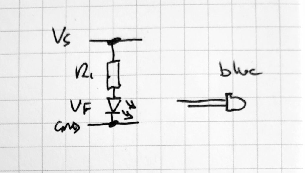
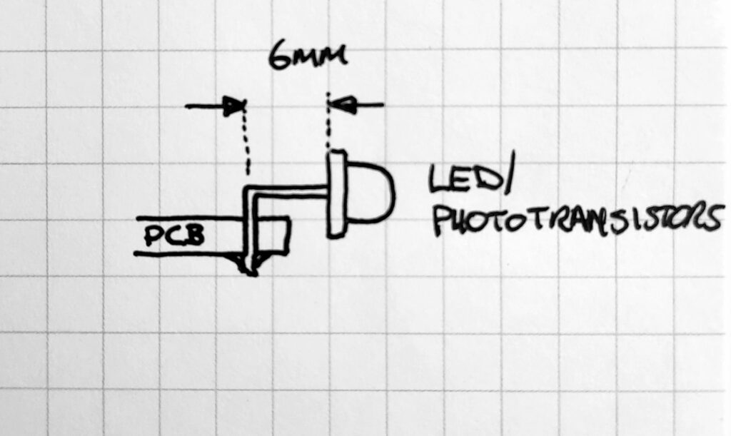
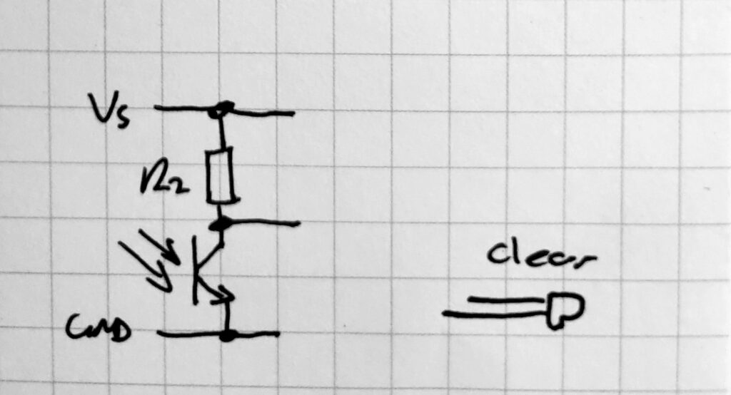
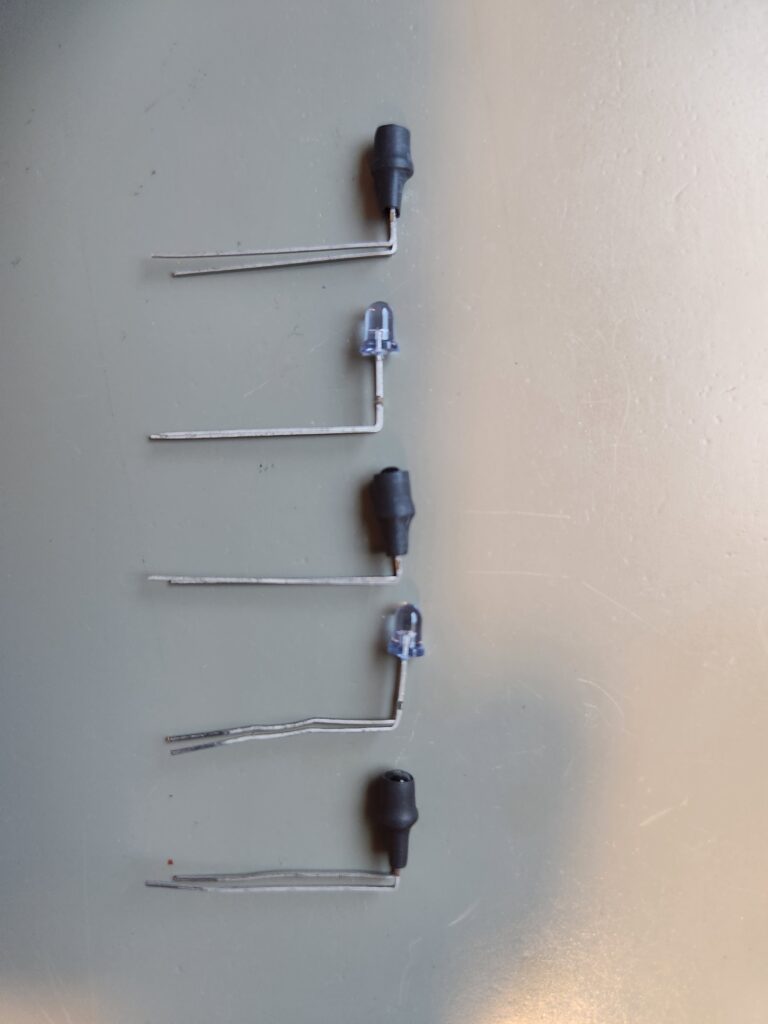
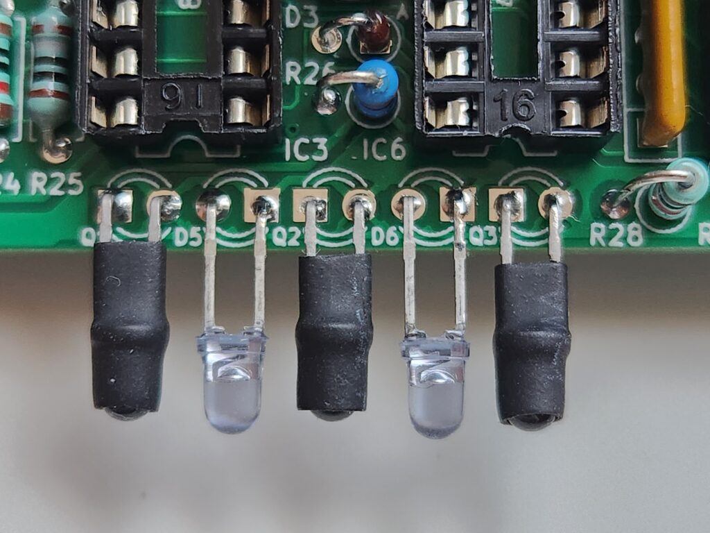
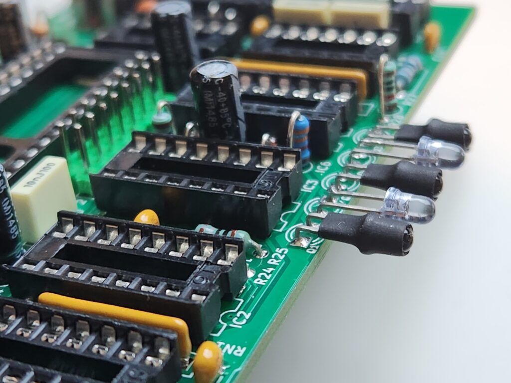
You’ll also note that the clone board above is missing the phototransistors/LEDs for line following. These were later bent and fitted according to the notes below (note that on the original board I have the legs are bent too short/too far away from the driving surface). Note also that the LEDs have blue tint to them and that the fitment in the board is reversed between phototransistors and photoLEDs. Finally note the heat-shrink tubing over the phototransistors to ensure they are only seeing reflected light from the surface below the robot.
Mechanical Design and Assembly
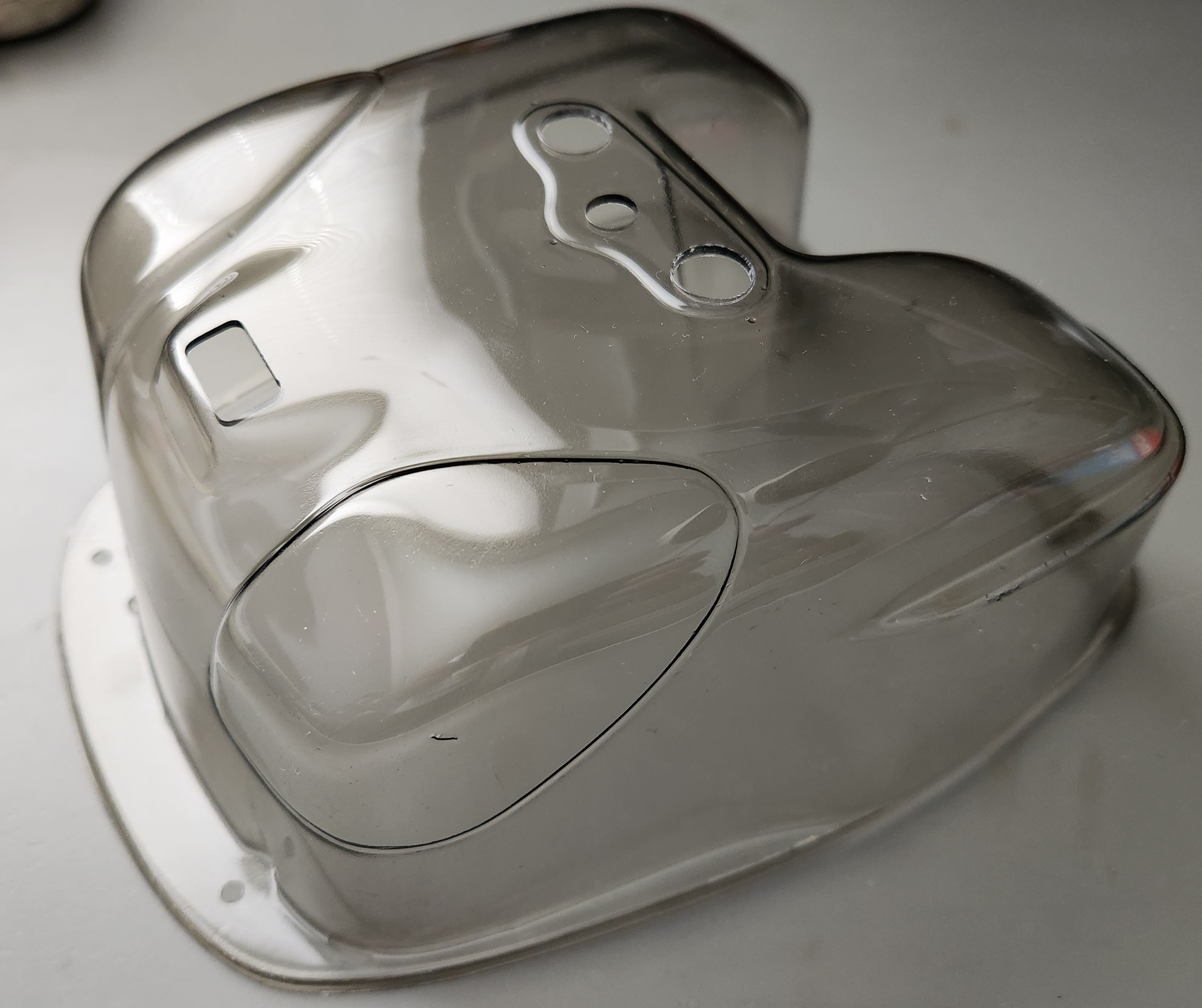
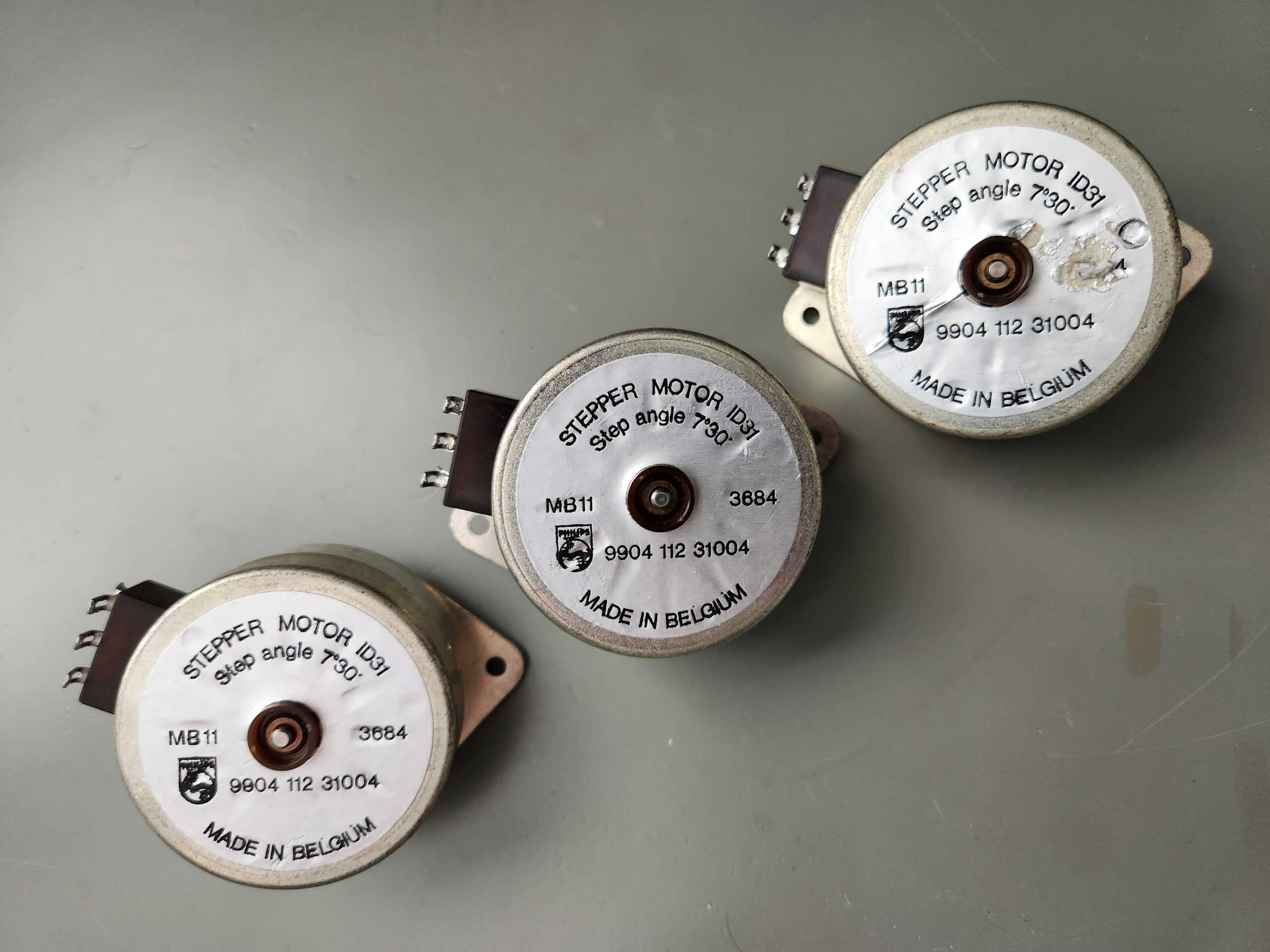
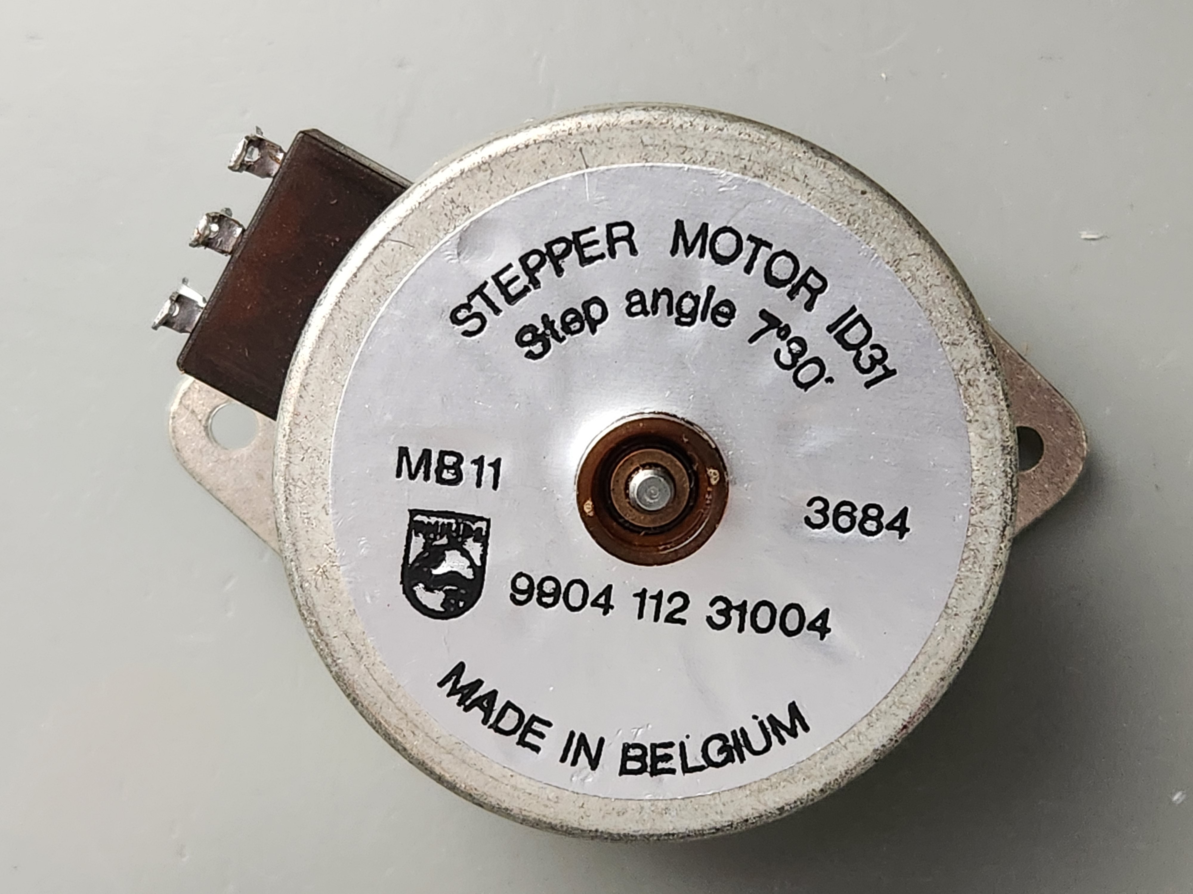
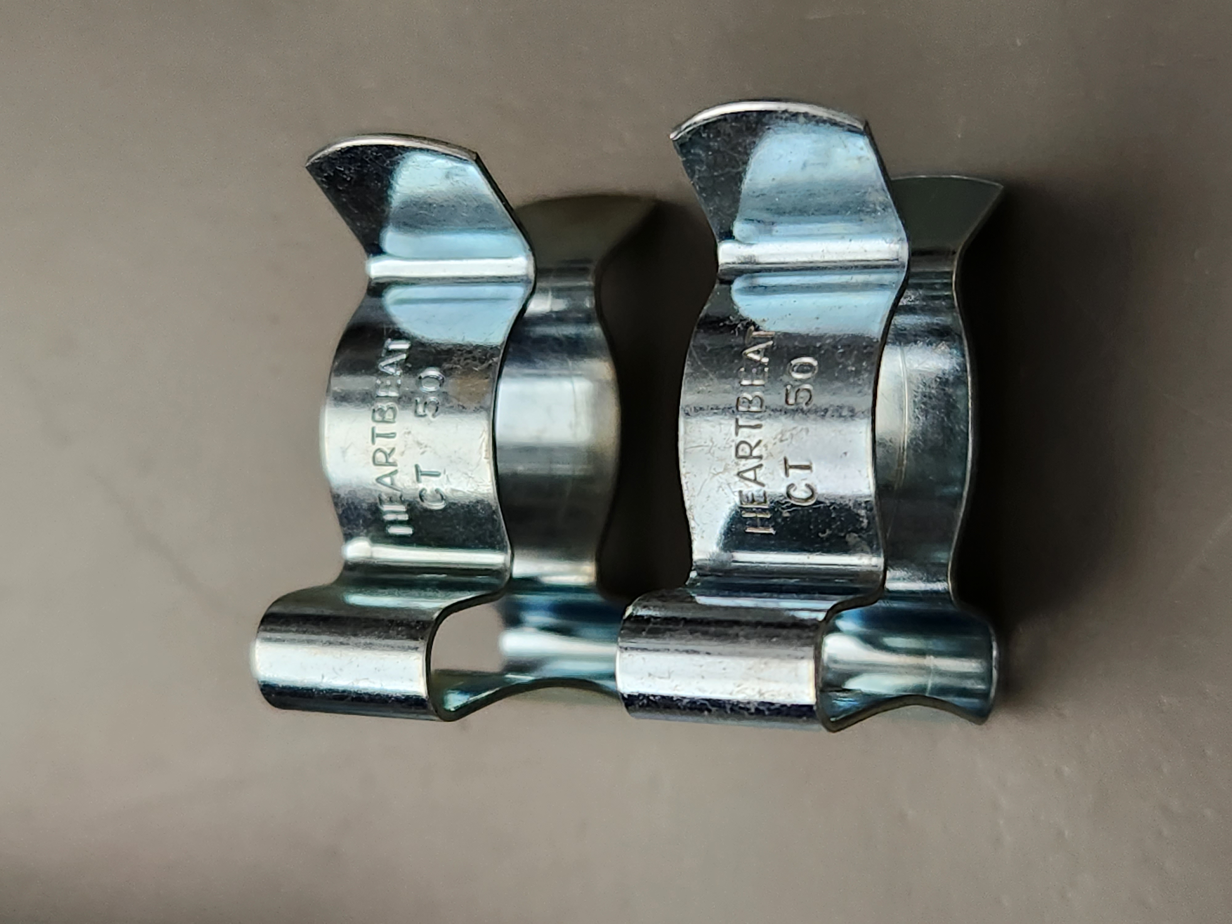
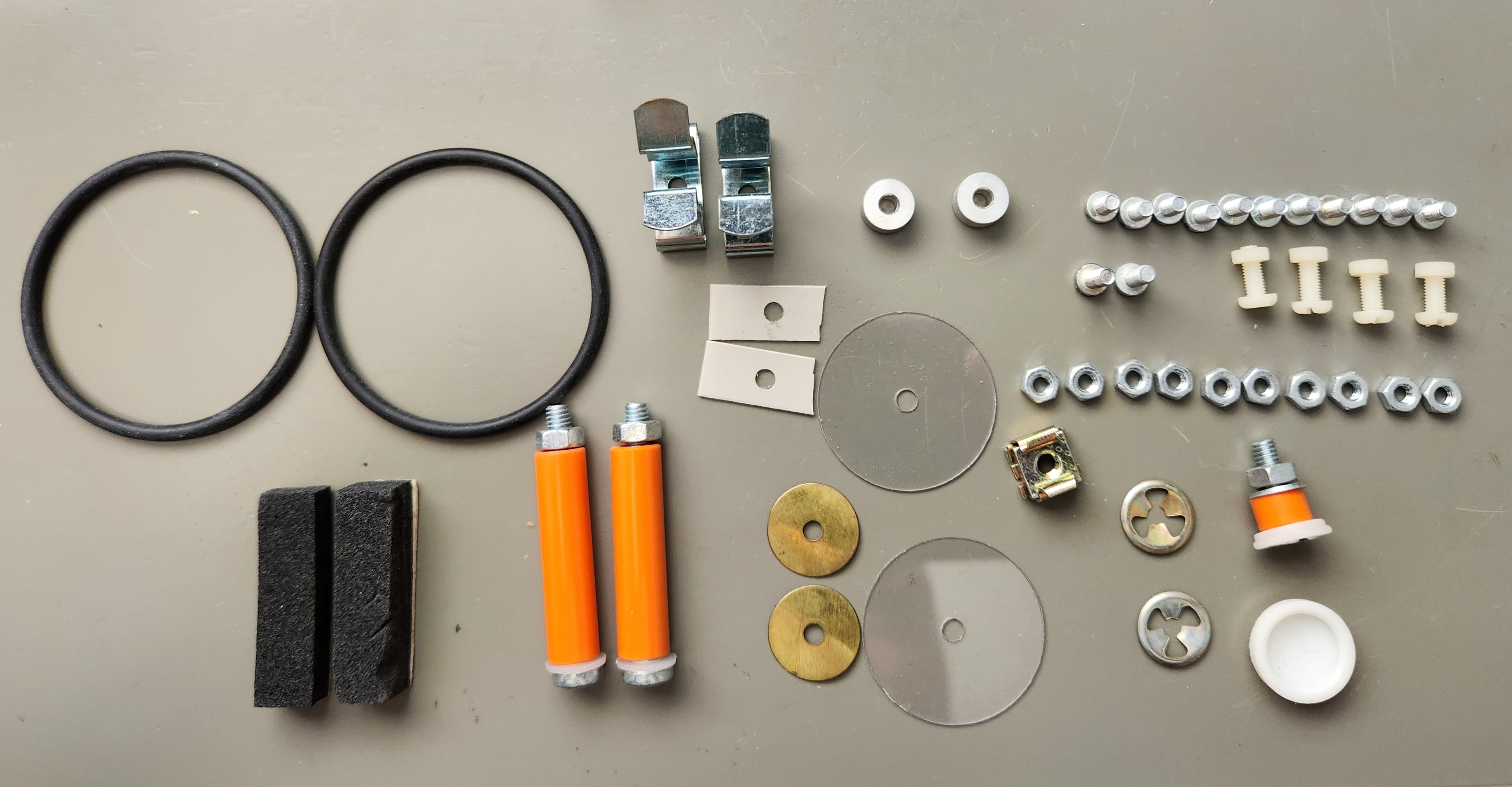
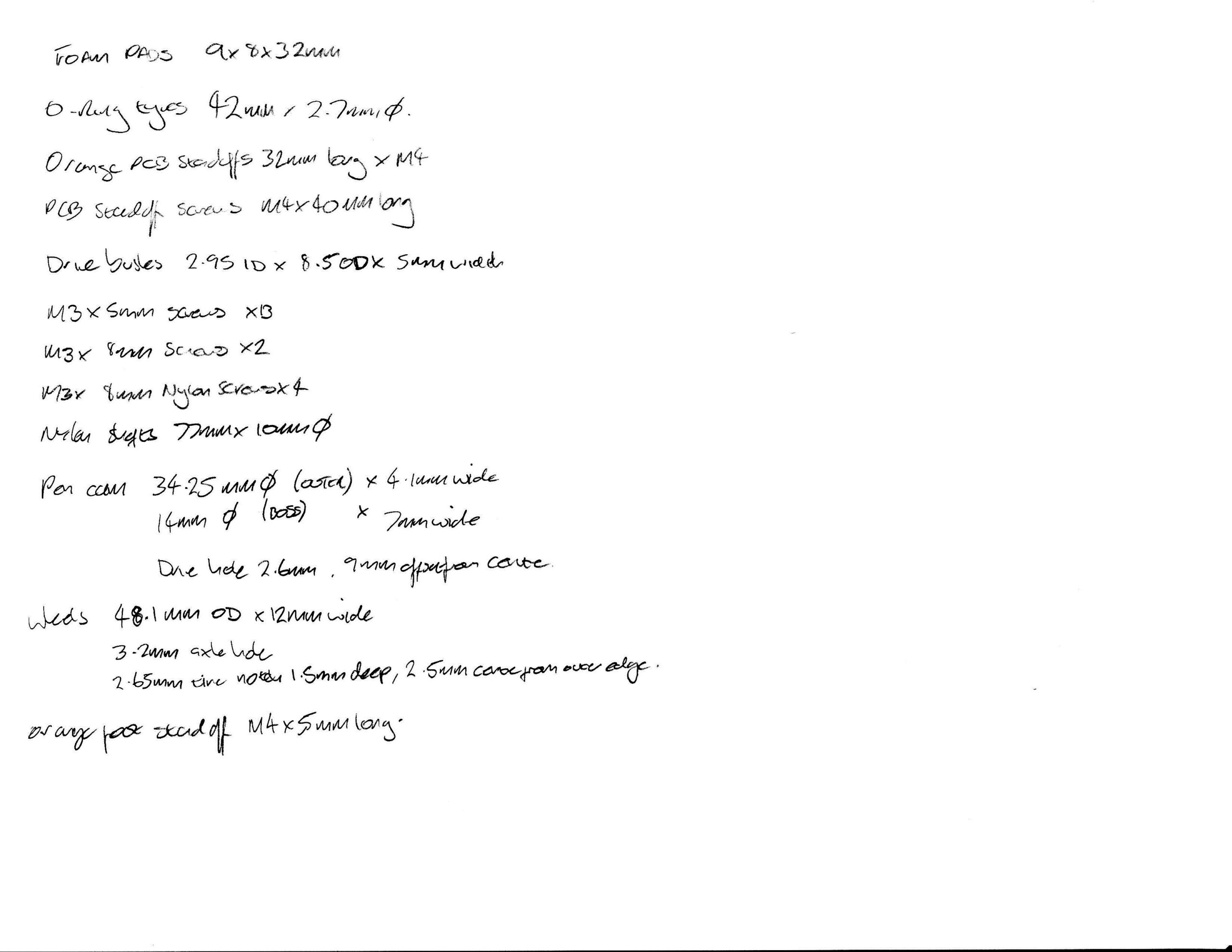
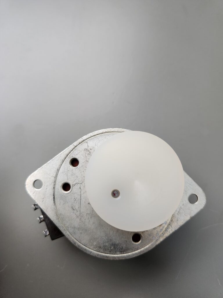
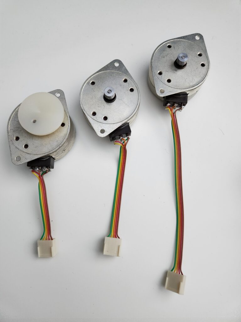
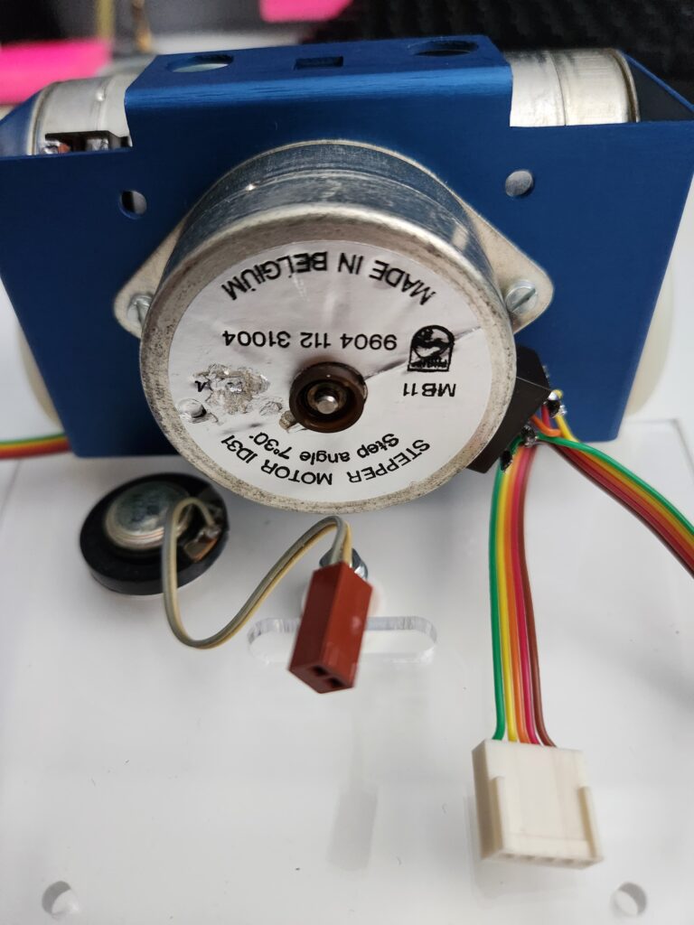
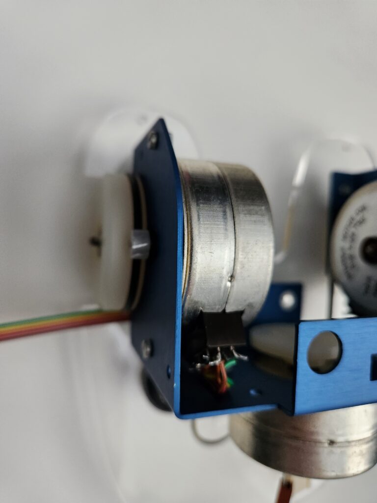
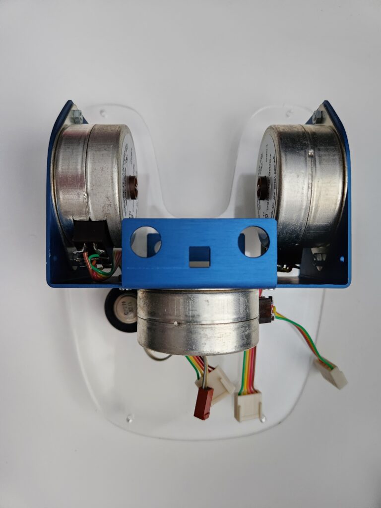
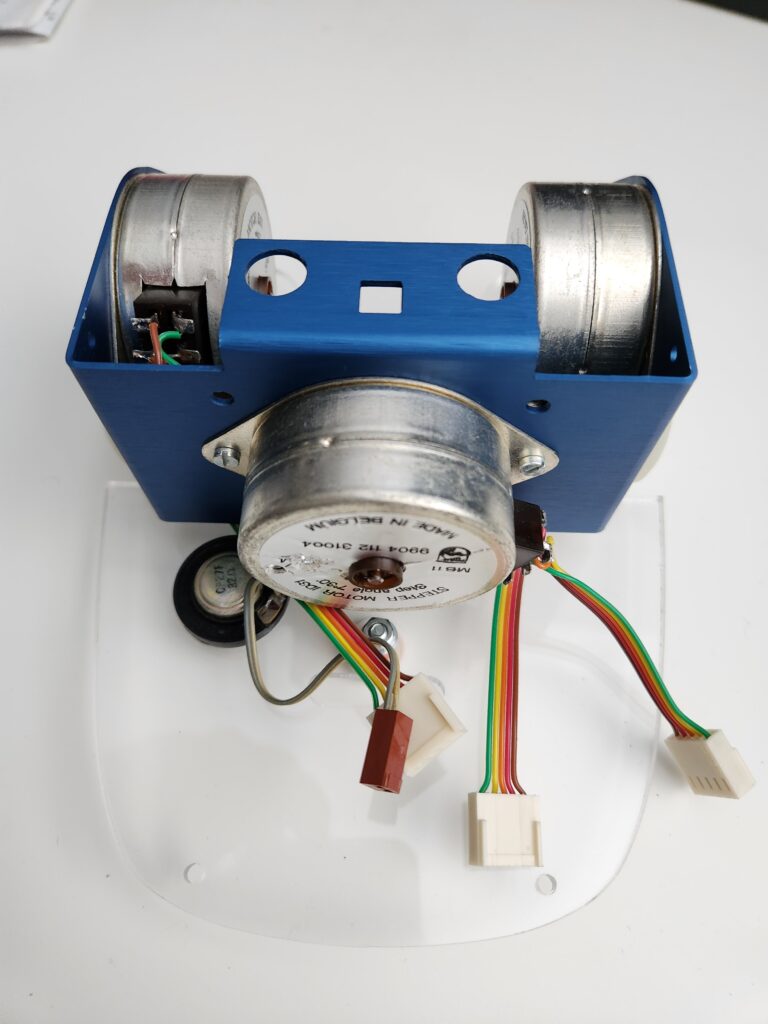
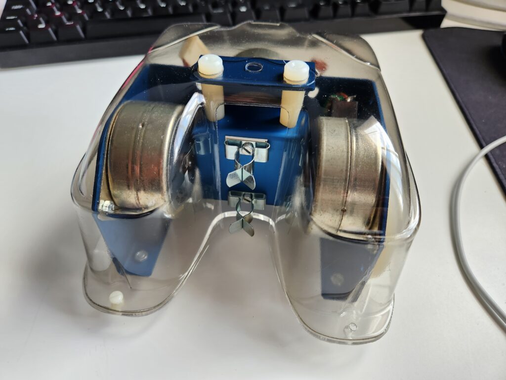
Let’s divert attention to the mechanical build. As mentioned I was fortunate enough to be able to source an original kit of parts. Here’s some photos prior to assembly and some notes/measurements taken at the same time. With the exception of the vacuum formed shell, I expect there’s now enough information here to re-create the whole design. One of the main difficulties in recreating this would be sourcing the Philips stepper motors. Long out of production there now seems to be only 1’s or 2’s of these available on eBay.
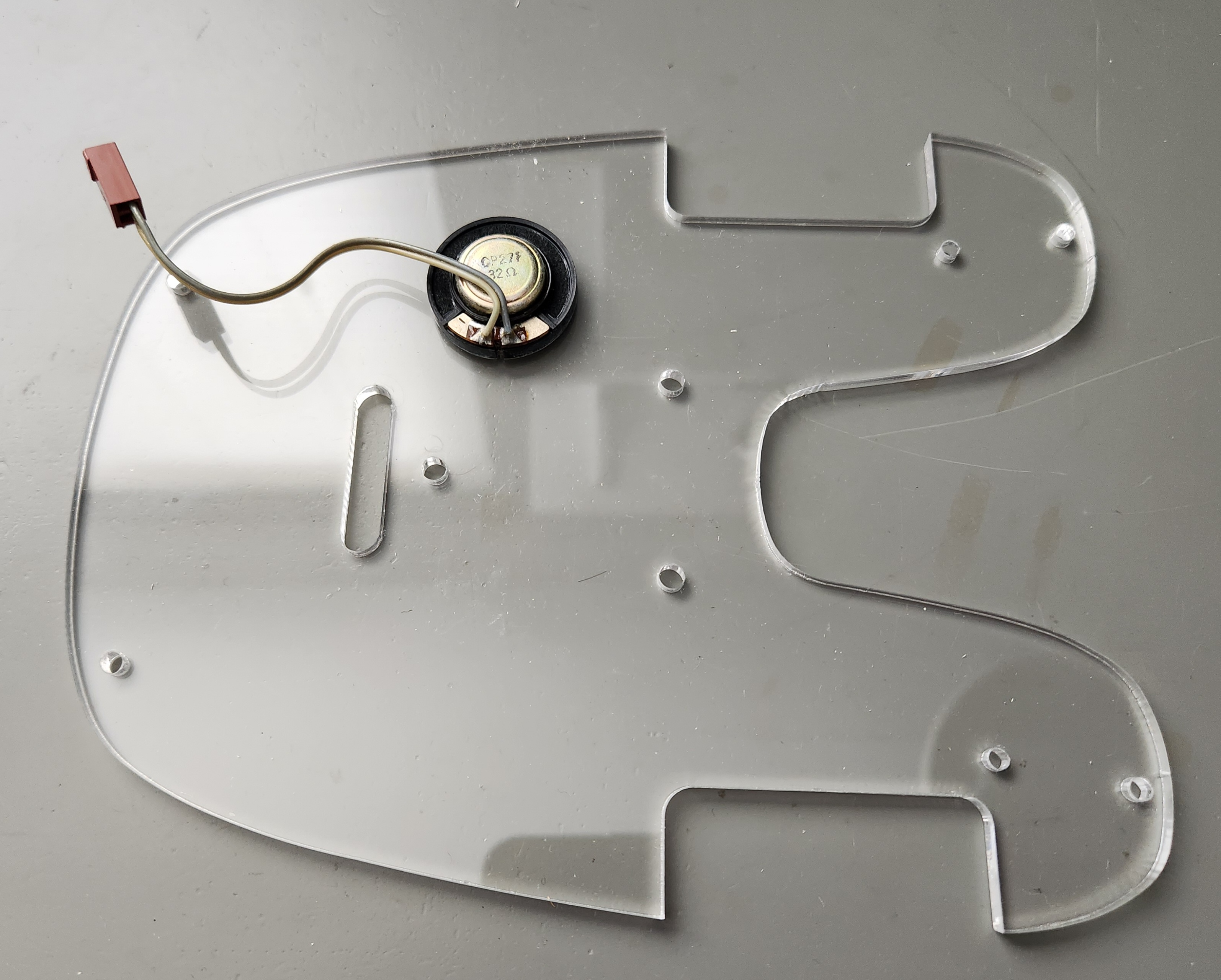
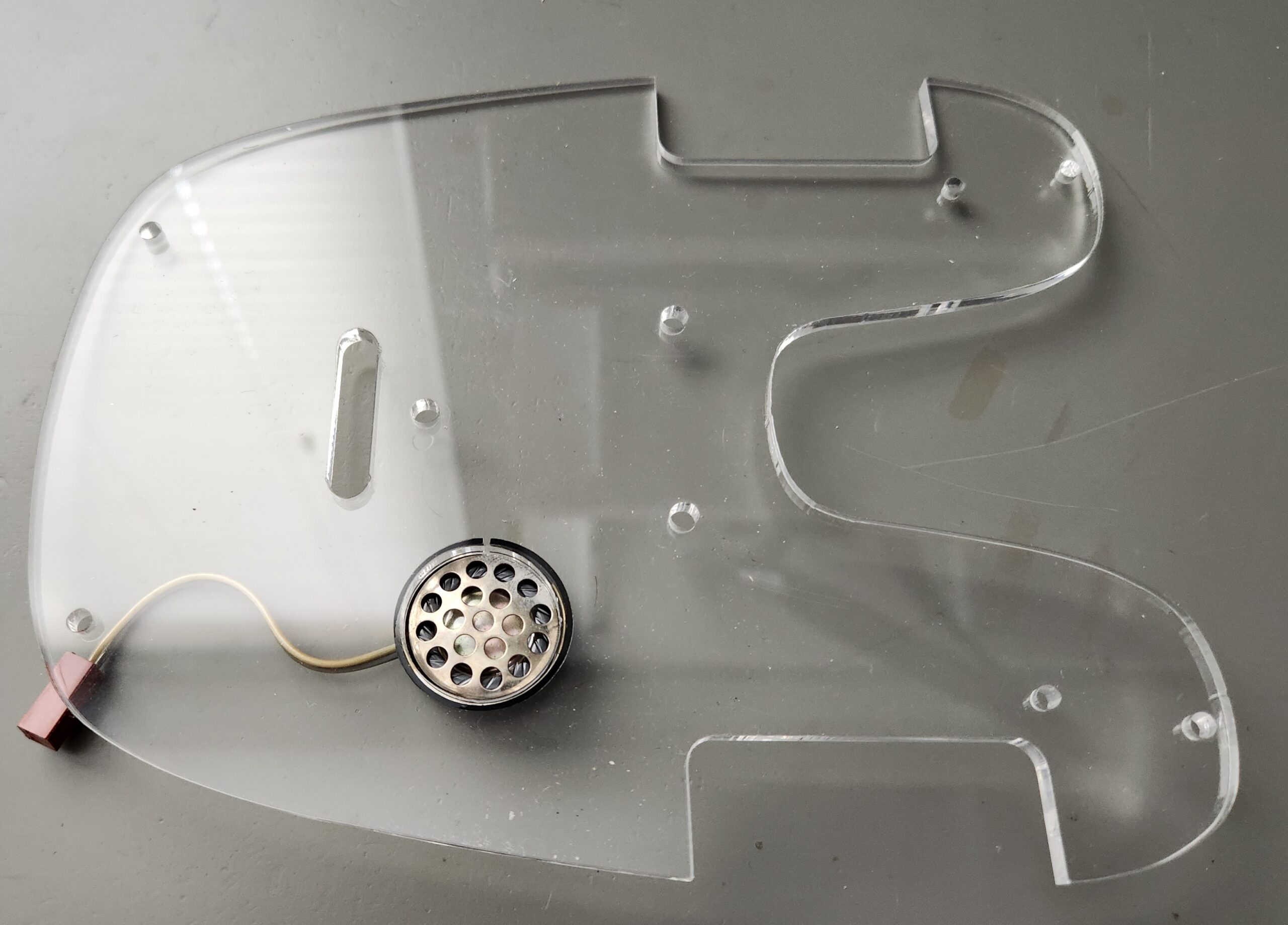
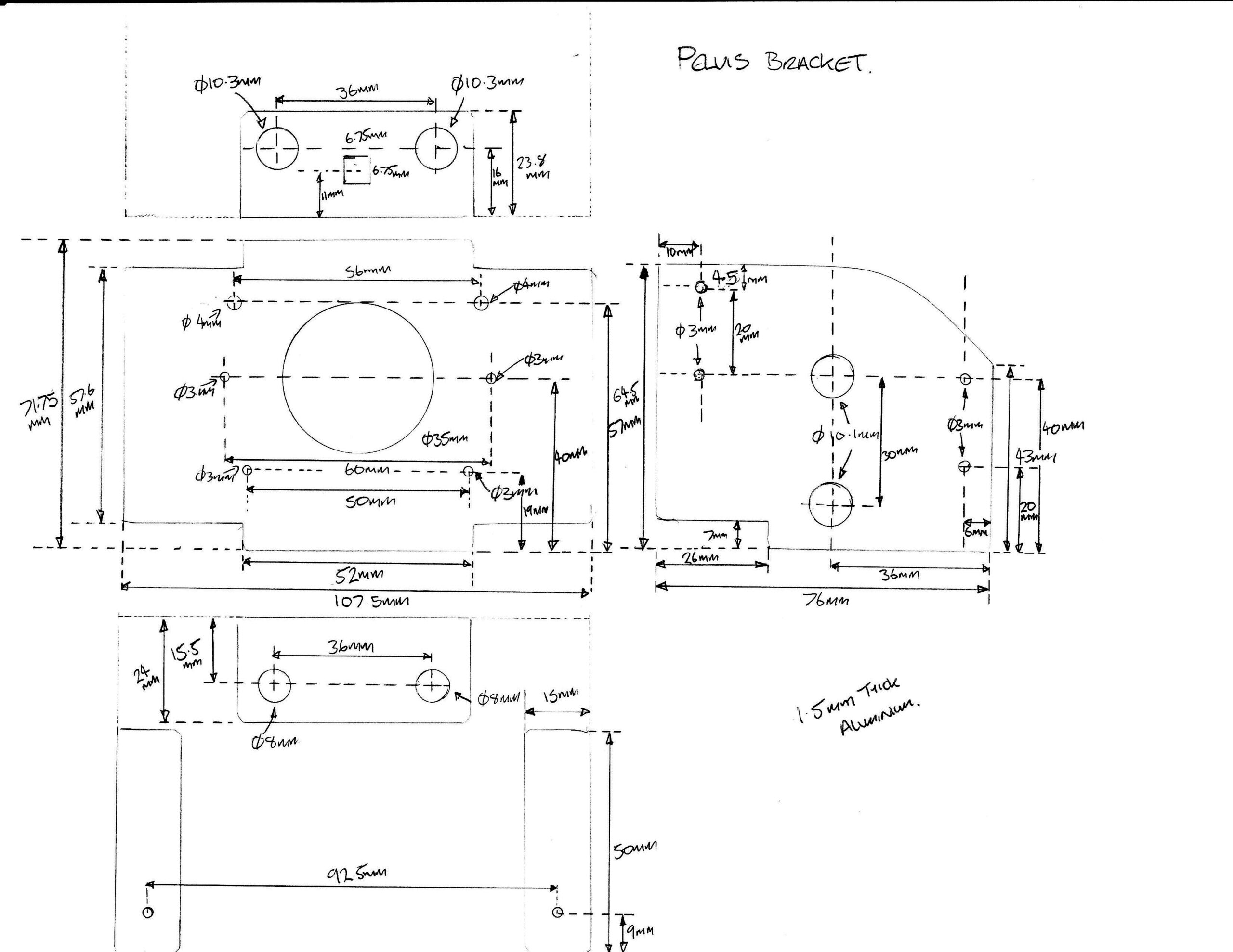
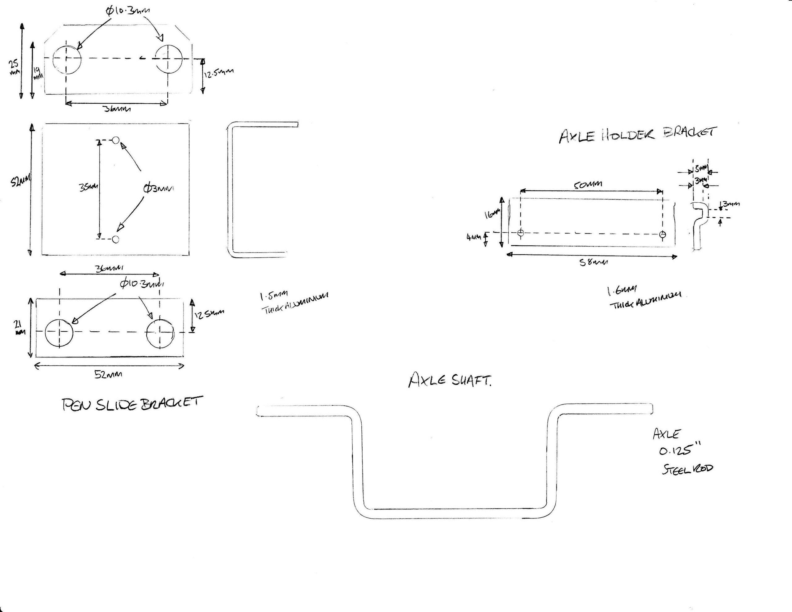
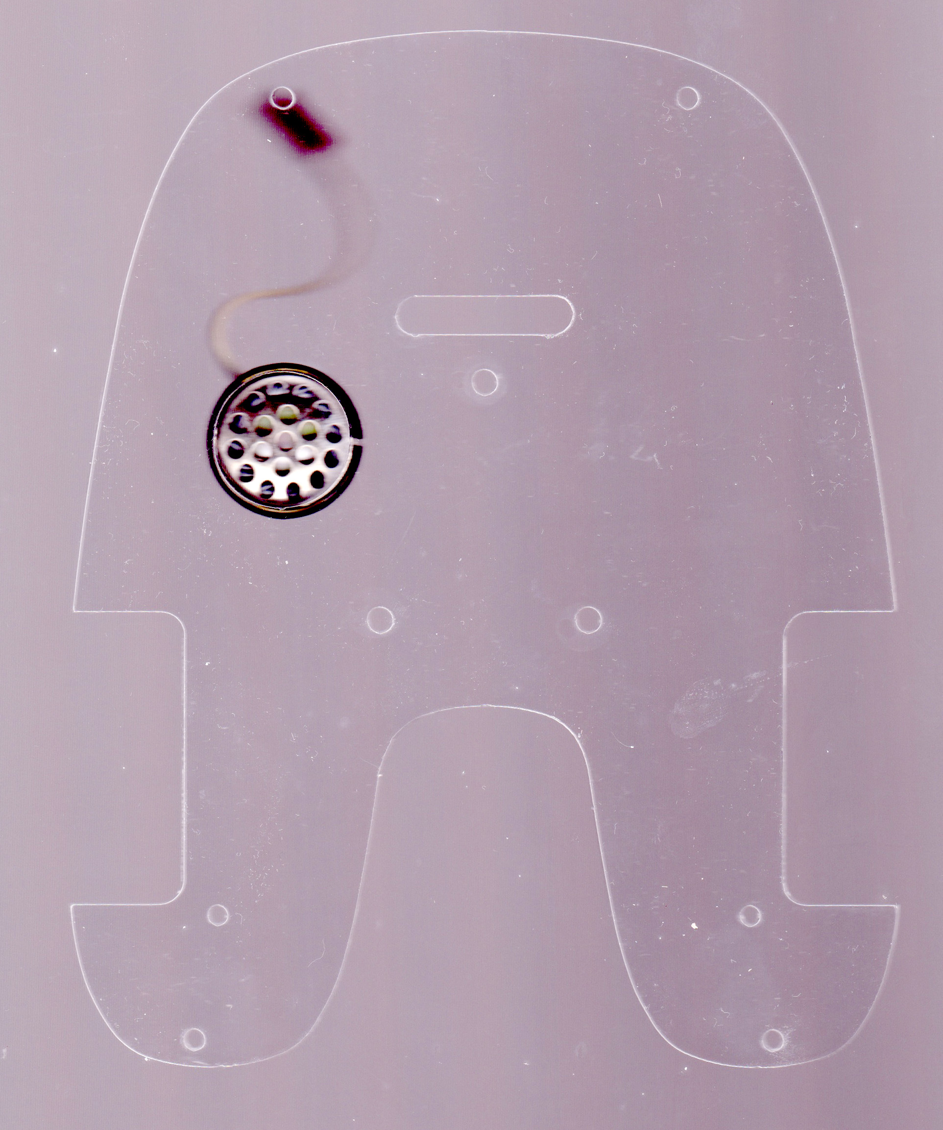
Here are my drawings and notes prior to assembly, to help others trying to build one of these. Note that the scan of the base is at 300dpi so it’s possible to take precise measurements from this, in fact all of these are at 300dpi, so the axle dimensions are also ascertainable from the outline drawing.
Mechanical Assembly
Mechanical assembly is fairly straightforward following the original instructions. I have attached below some notes that David sent me with the parts, take note of some of this especially around the motor drive bosses, plastic leafs for the pen clips, large plastic washers (inner) and brass shim washers (outer) for the wheels.
Additional Assembly Notes
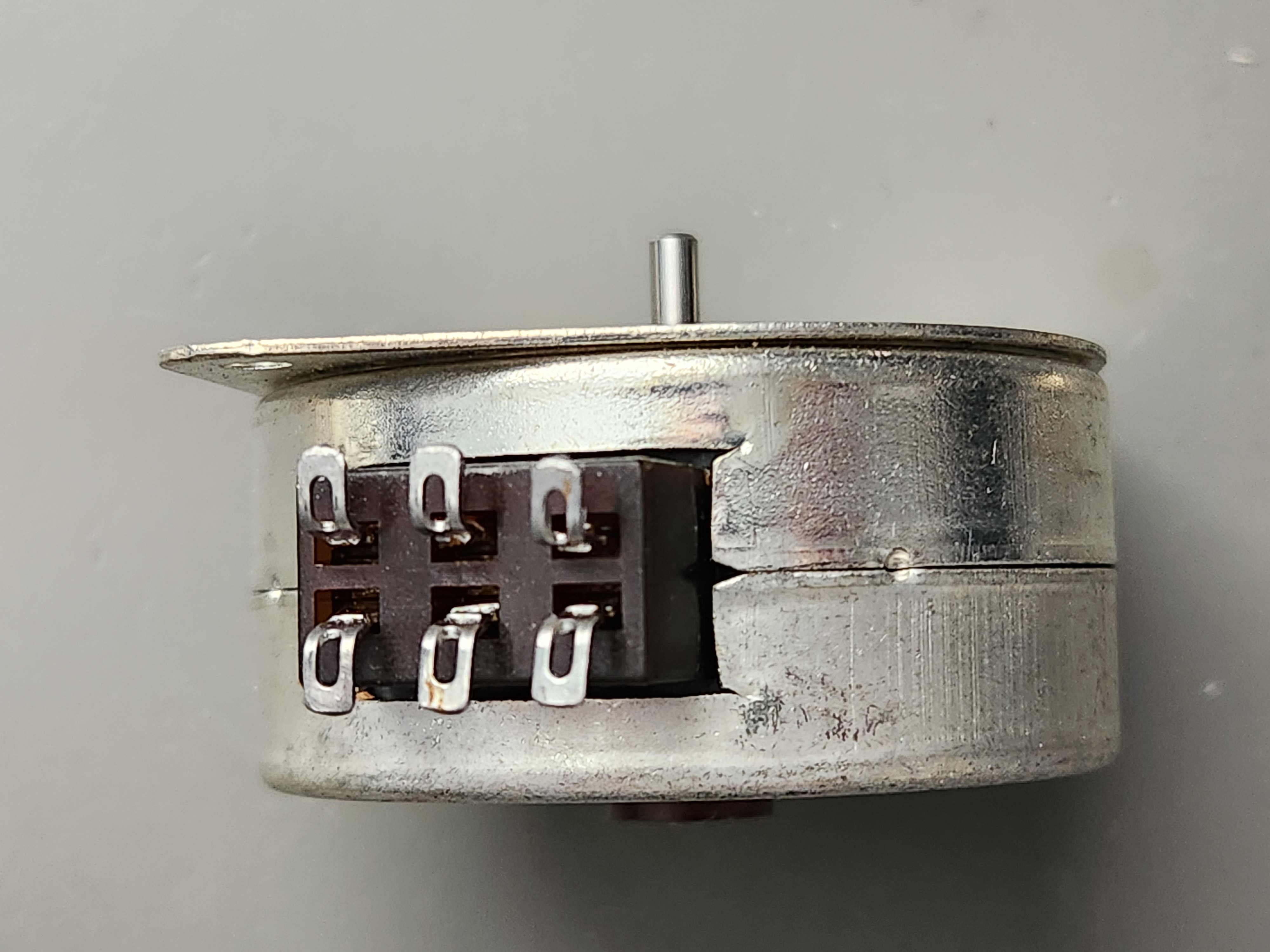
The wire lengths for the motors and wiring are on David’s website. Included below are my own notes for the wiring. Note that all motors are wired identically so the right motor is actually driven in reverse due to the nature of the pin order being reversed at the PCB.
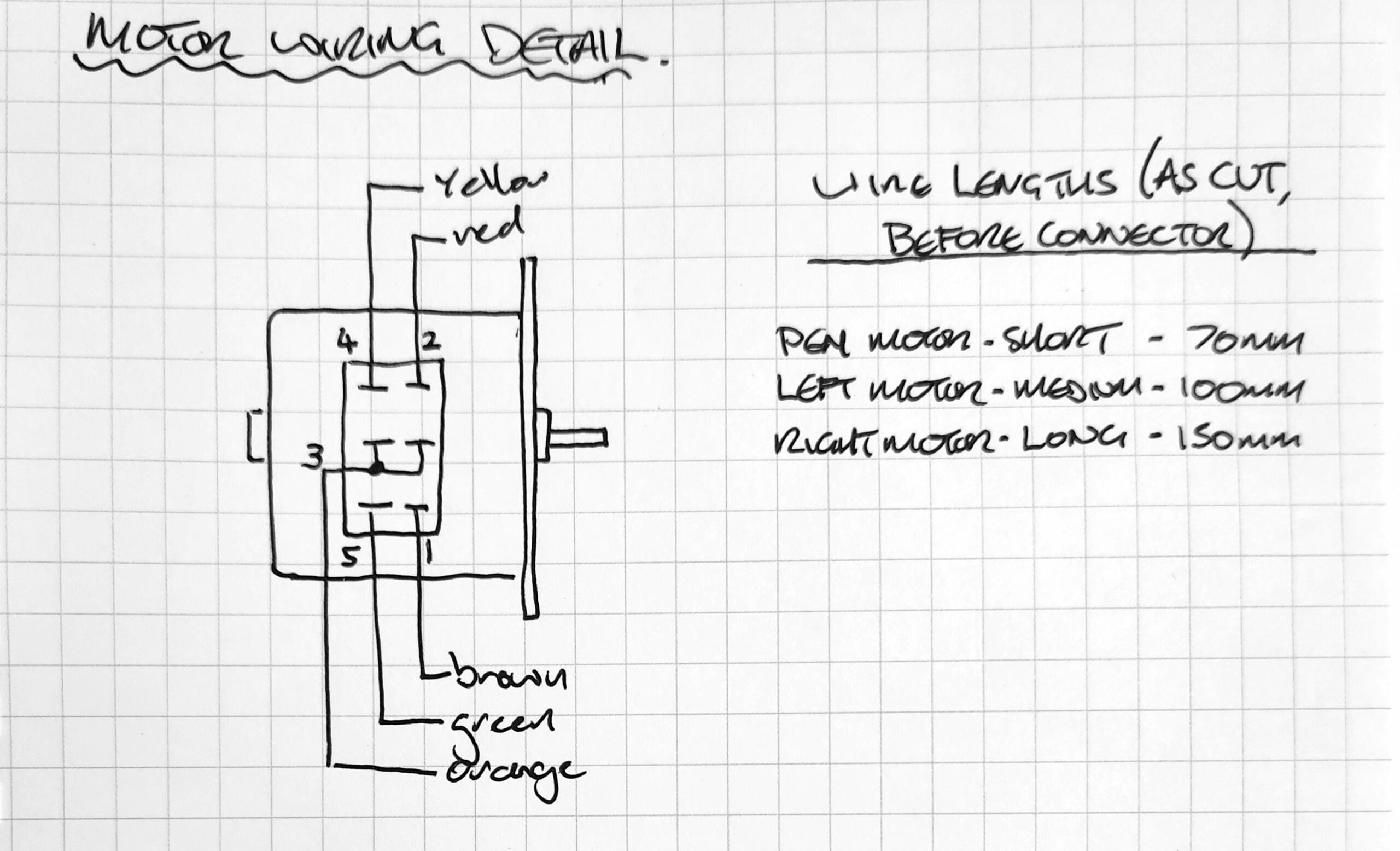
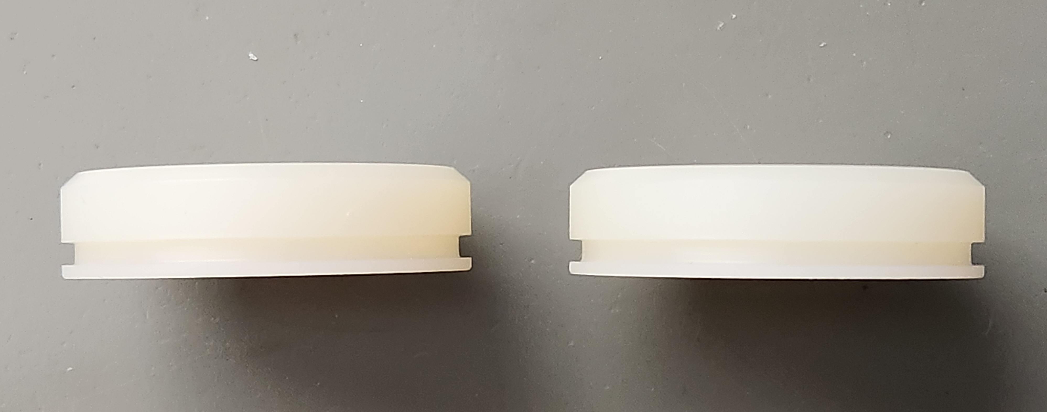
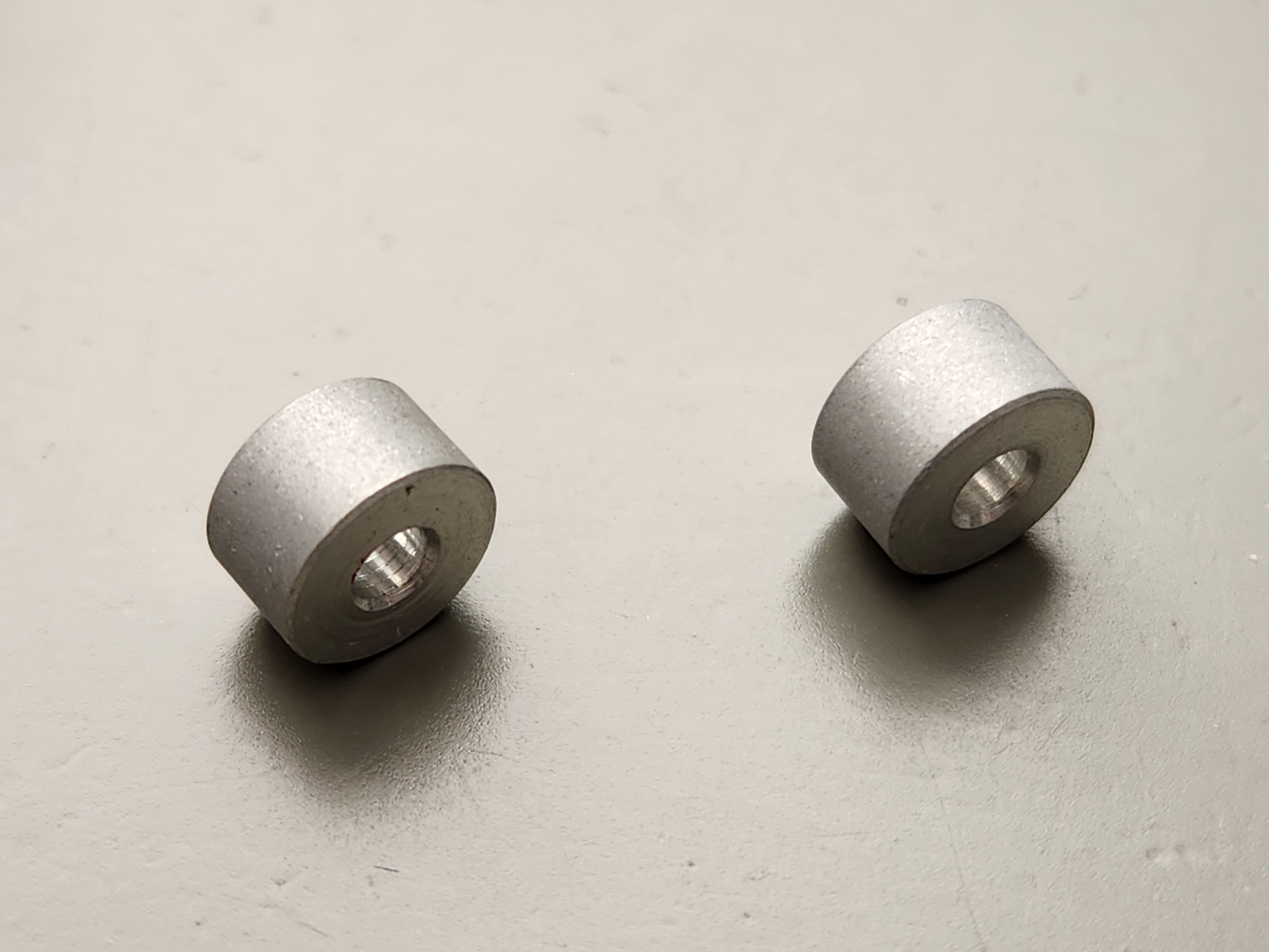
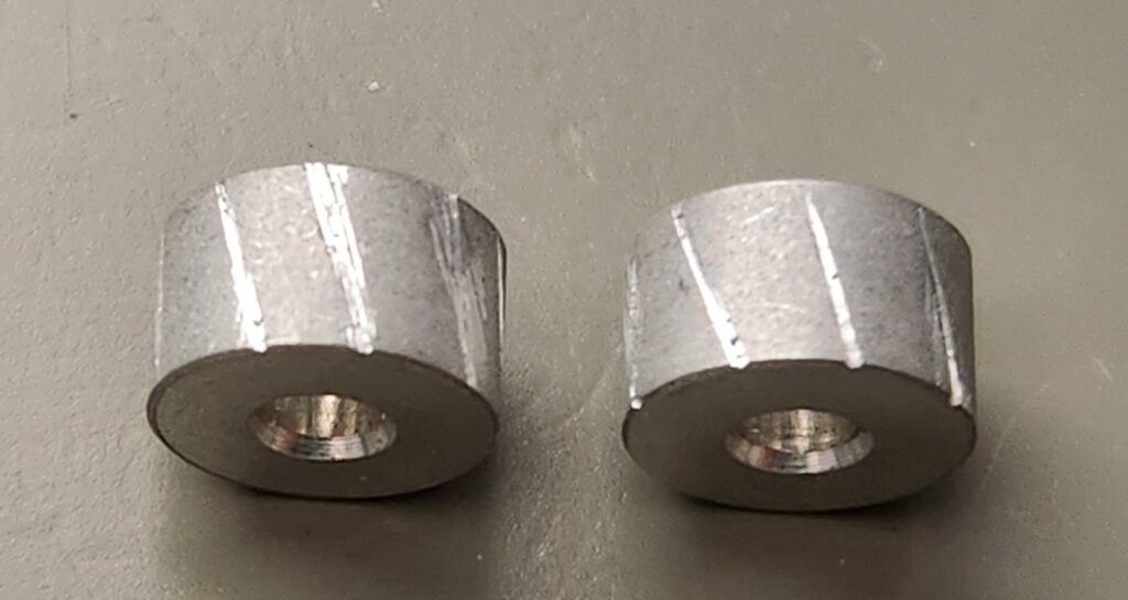
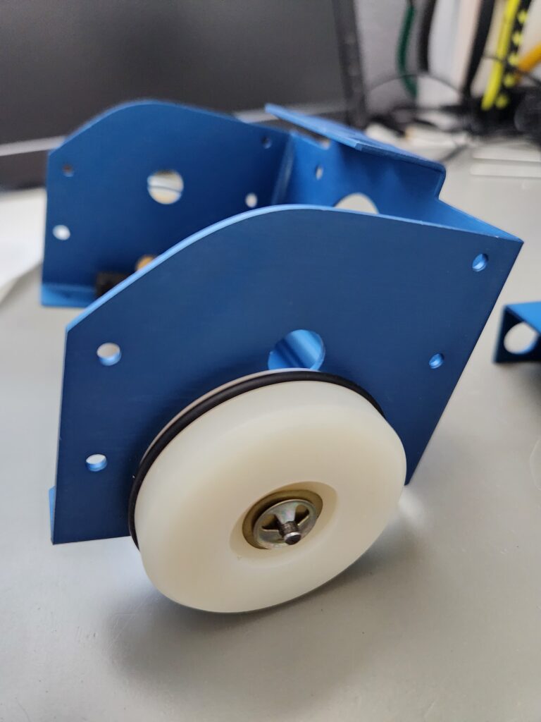
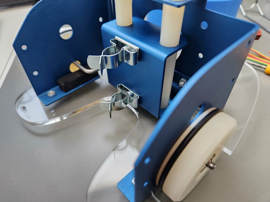
The drive bosses are grit blasted but may need more scratches going across the rim (in my case I added some diagonal score marks with a sharp-edged needle file (look closely at the pictures and video later). The drive bosses need fixing on the motor shafts with Loctite or similar – don’t let it get into the motor bearing. The nylon screws and nuts are for the shell.
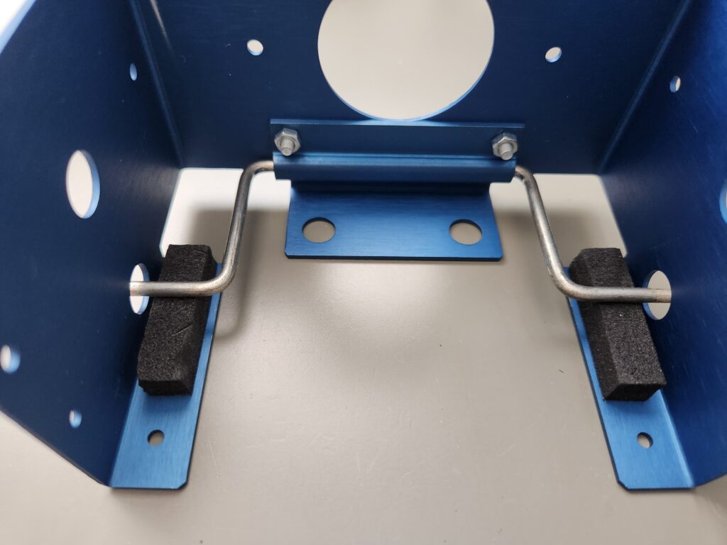
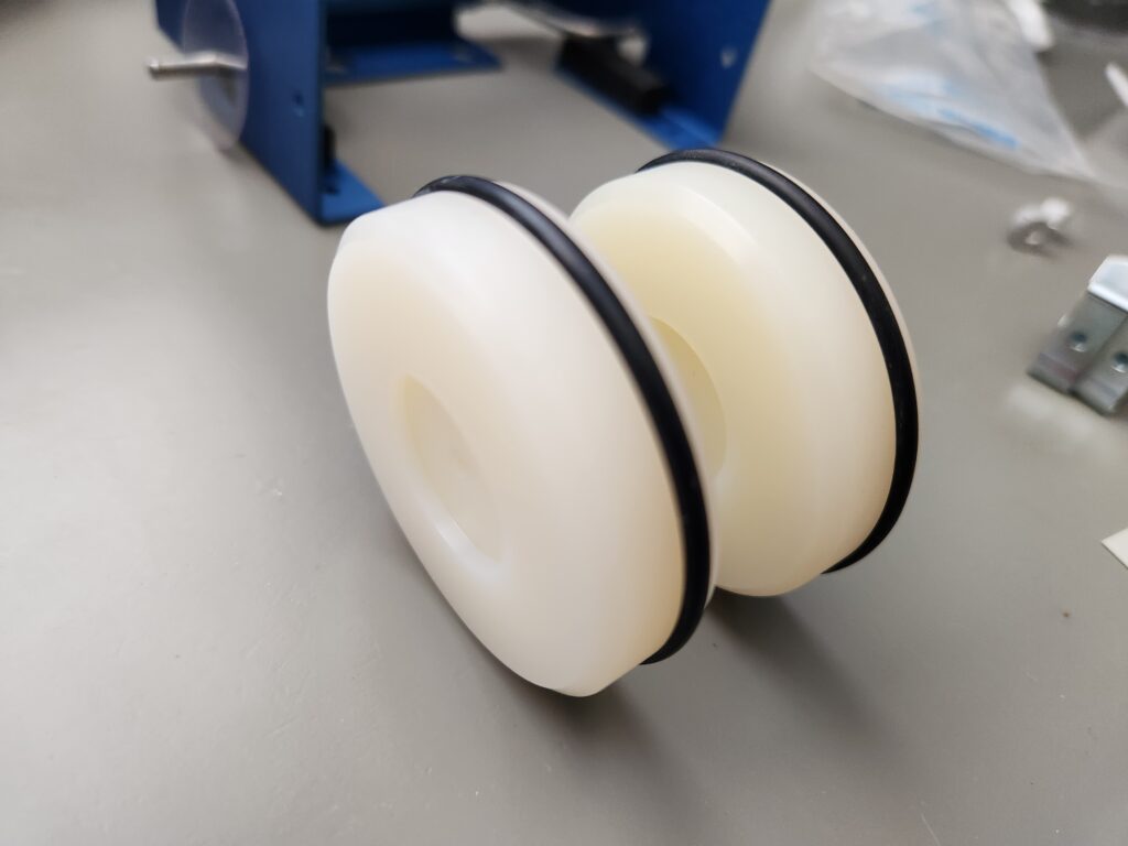
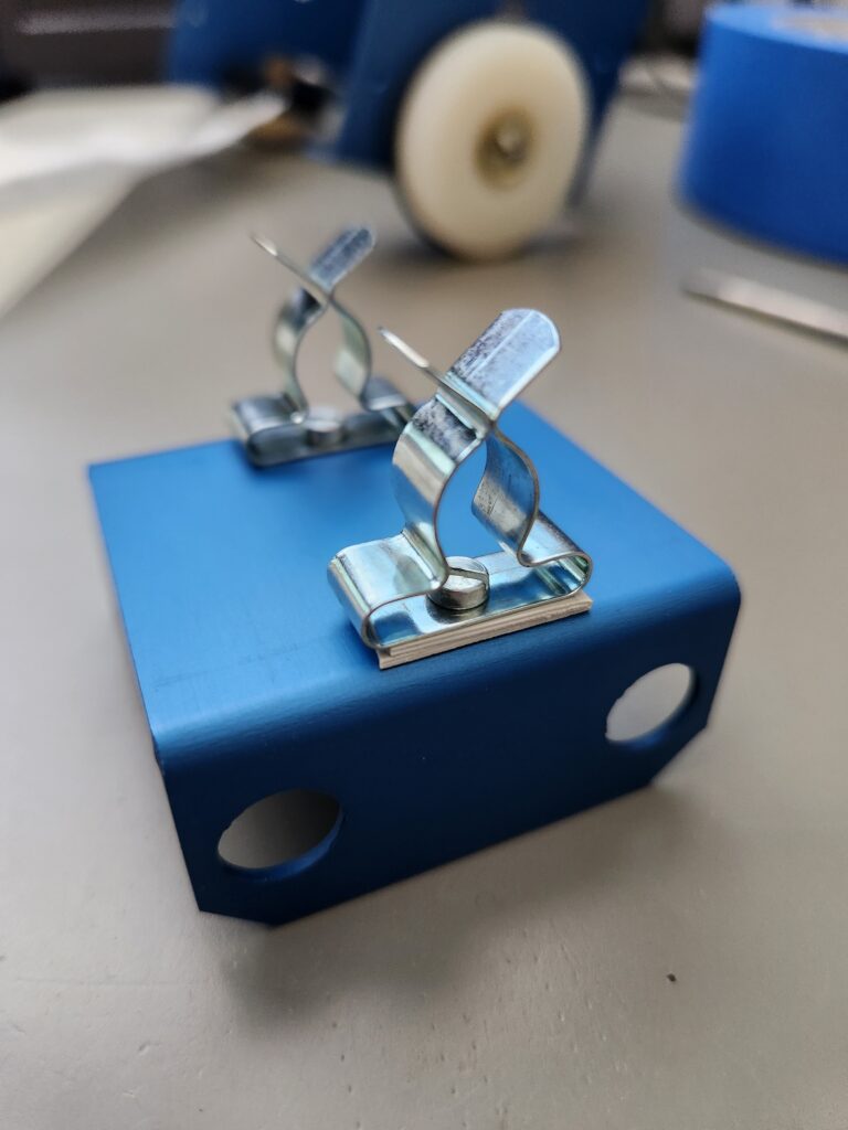
The grey plastic leafs are to pad out the top pen clip so the tip of the pen is on the wheel centre line (trial and error). The axle should be slightly loose under the fixing plate (which should be tight) so it can tip. The big clear plastic washers go between the wheels and the pelvis. The black foam blocks go under the axles where the go through the frame to add a little bit of pressure pushing the tyres against the drive bosses (it’s also possible that some plastic shims may be needed between the foam and the axle to limit foam deformation and put more pressure between the tyres and the drive bosses. When pushing on the wheels’ speed-nuts only slightly deform the brass shim curved washers just so there is no play.
A note on connectors: Zero2 actually uses QL joystick connectors NOT QL serial connectors on the original interface but these are pretty unobtainable these days (as mentioned at the beginning). Additional note from David: Sinclair originally wanted to use BT plugs but BT refused so he went with, custom for Sinclair, ‘W’ polarisation plugs instead of the BT ‘P’ polarisation. Serial and Joystick are both ‘W’ polarisation, one right handed and and the other left handed.
The standard/original kit of parts contains
- Nuts and bolts (M3 x 5,6,8 mm)
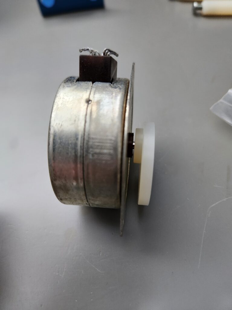
- 3 motors
- 1 perspex chassis / base plate
- 1 shell
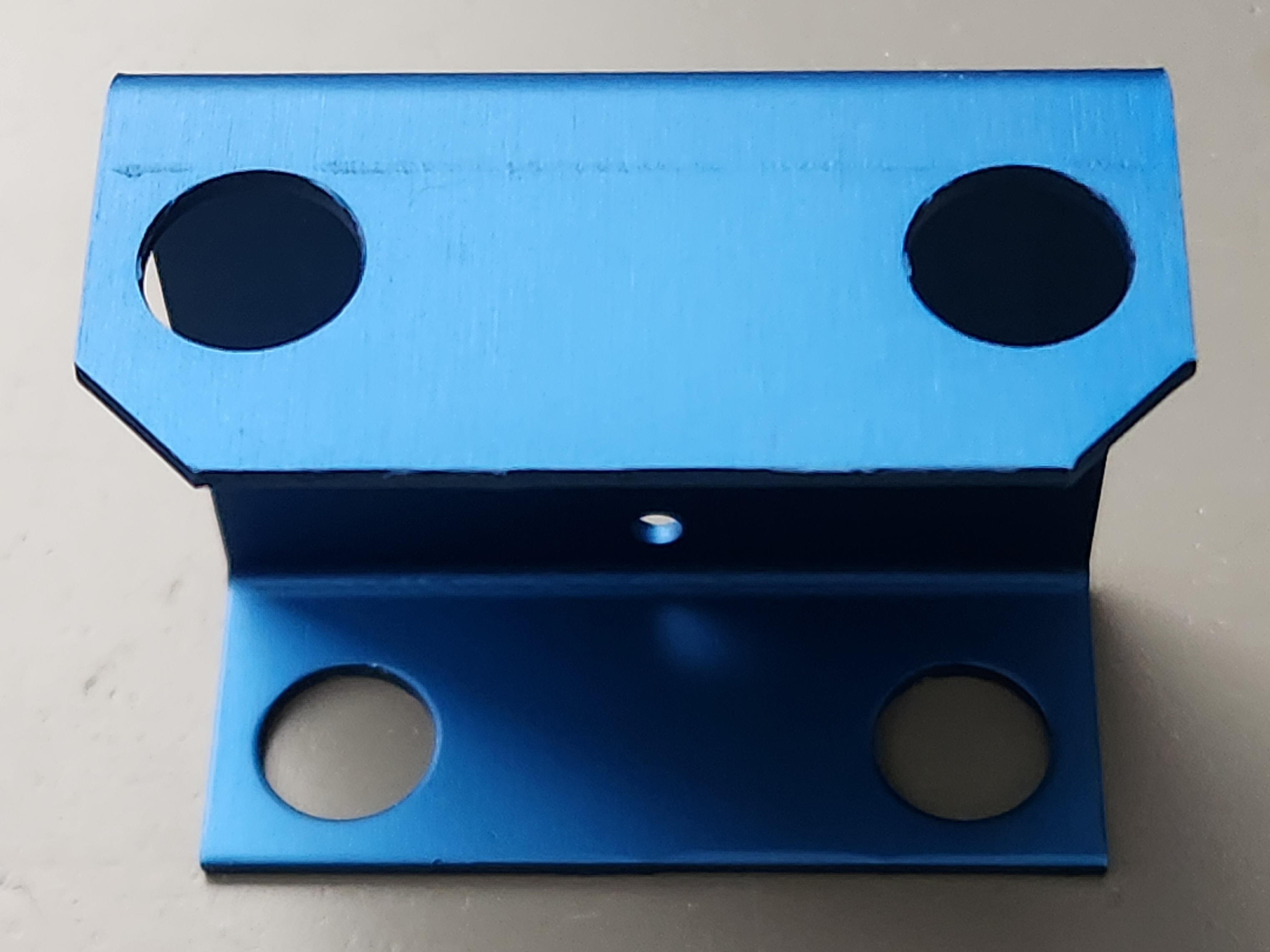
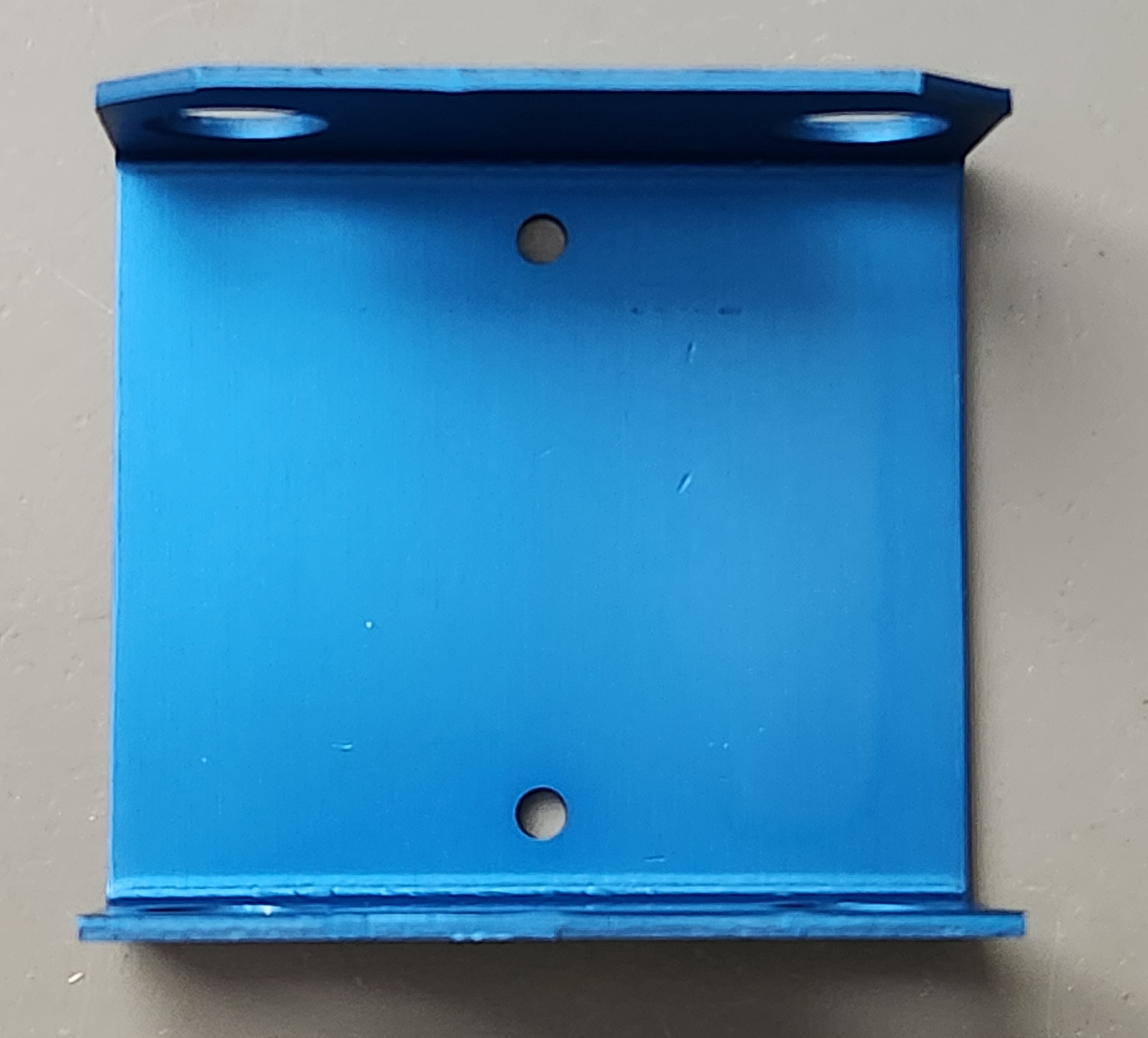
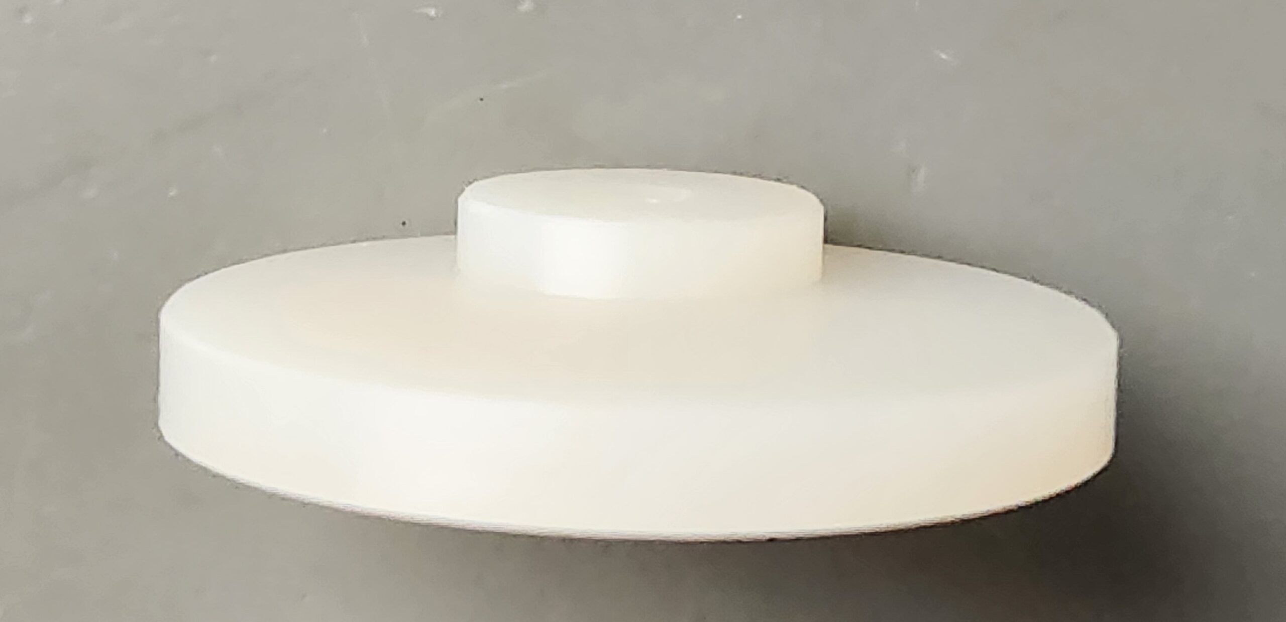
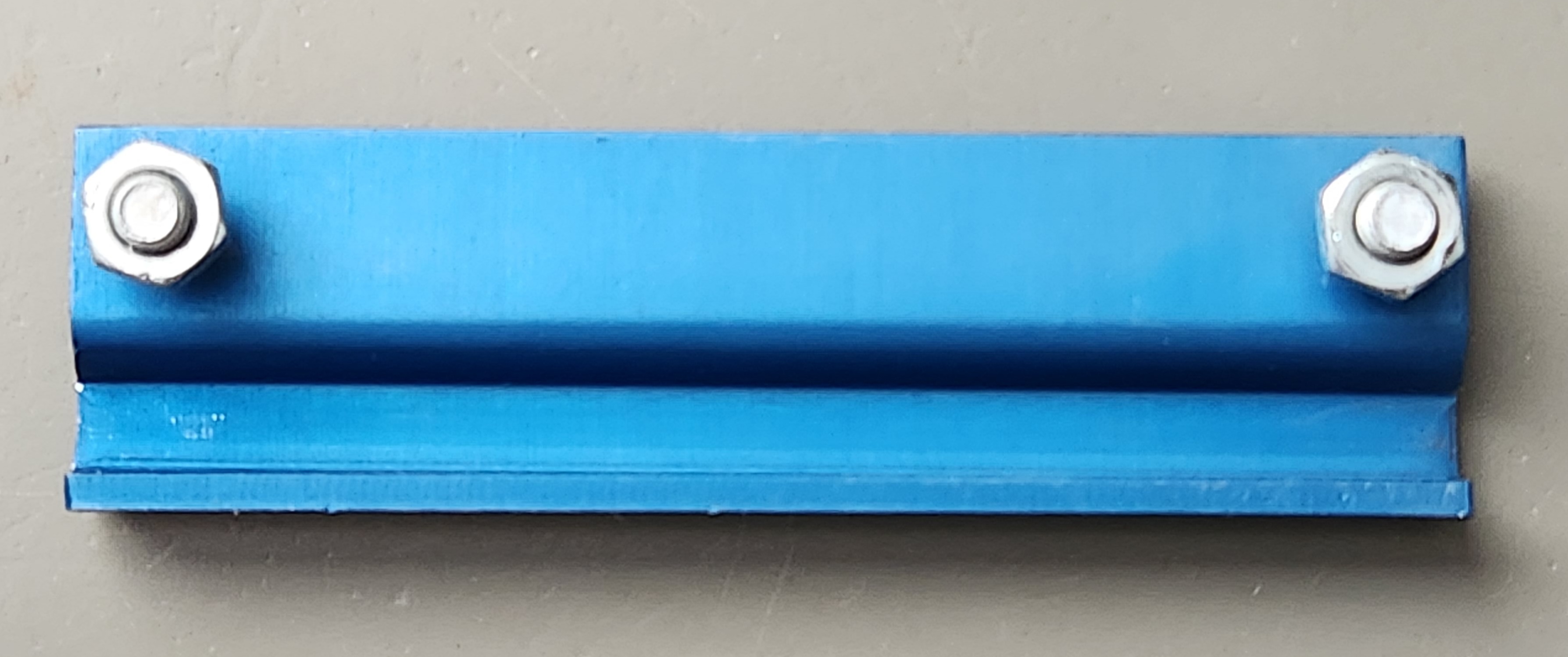
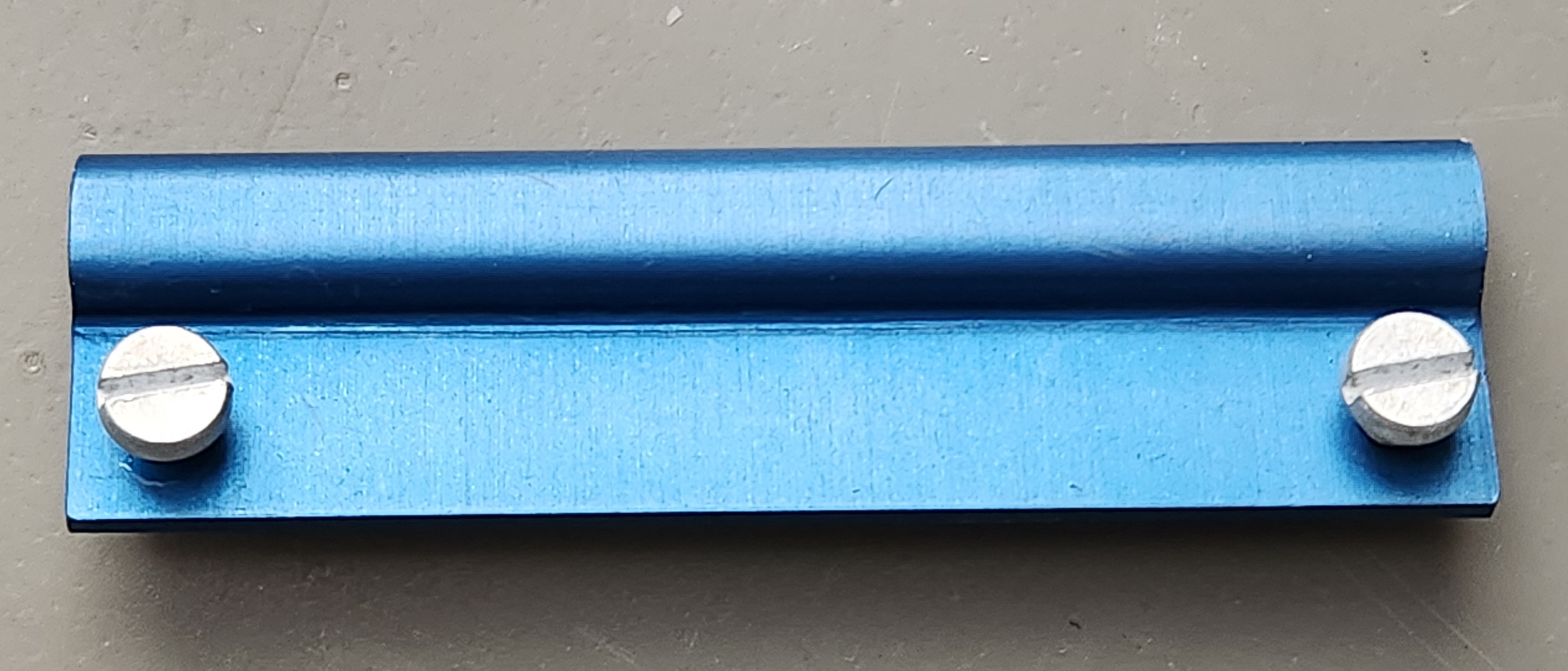
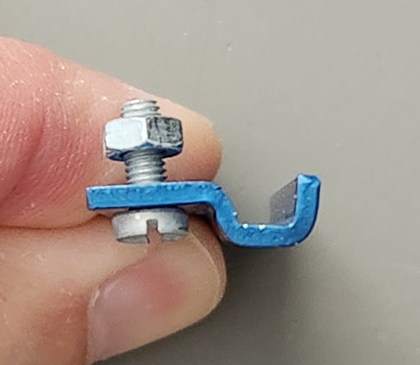
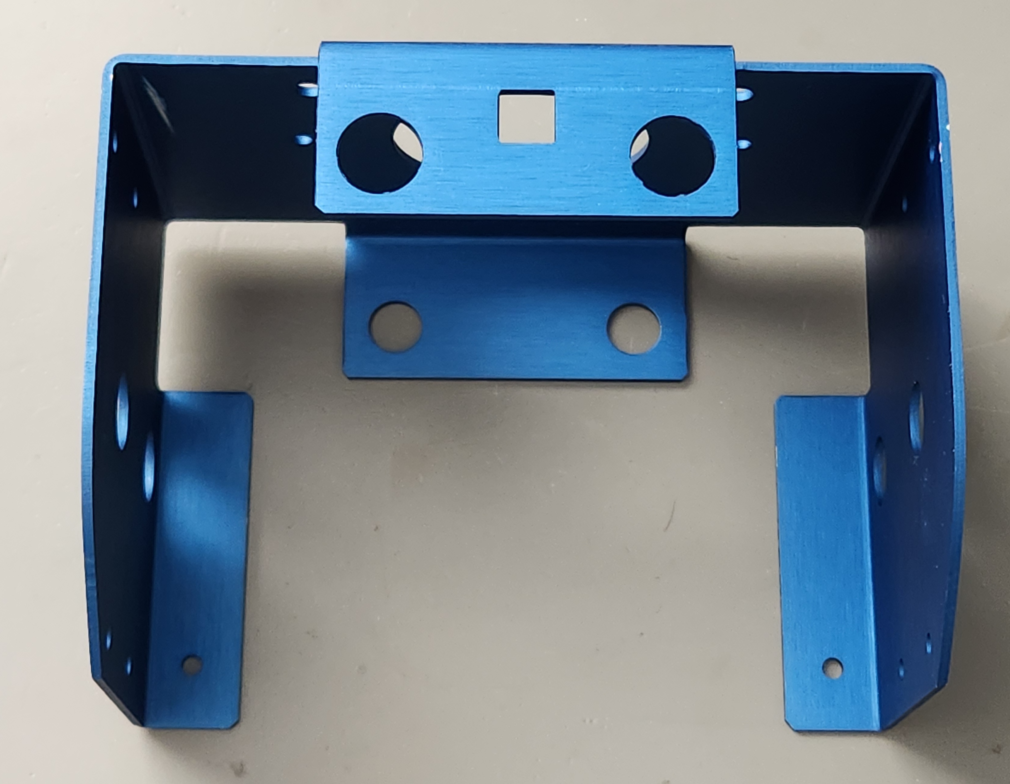
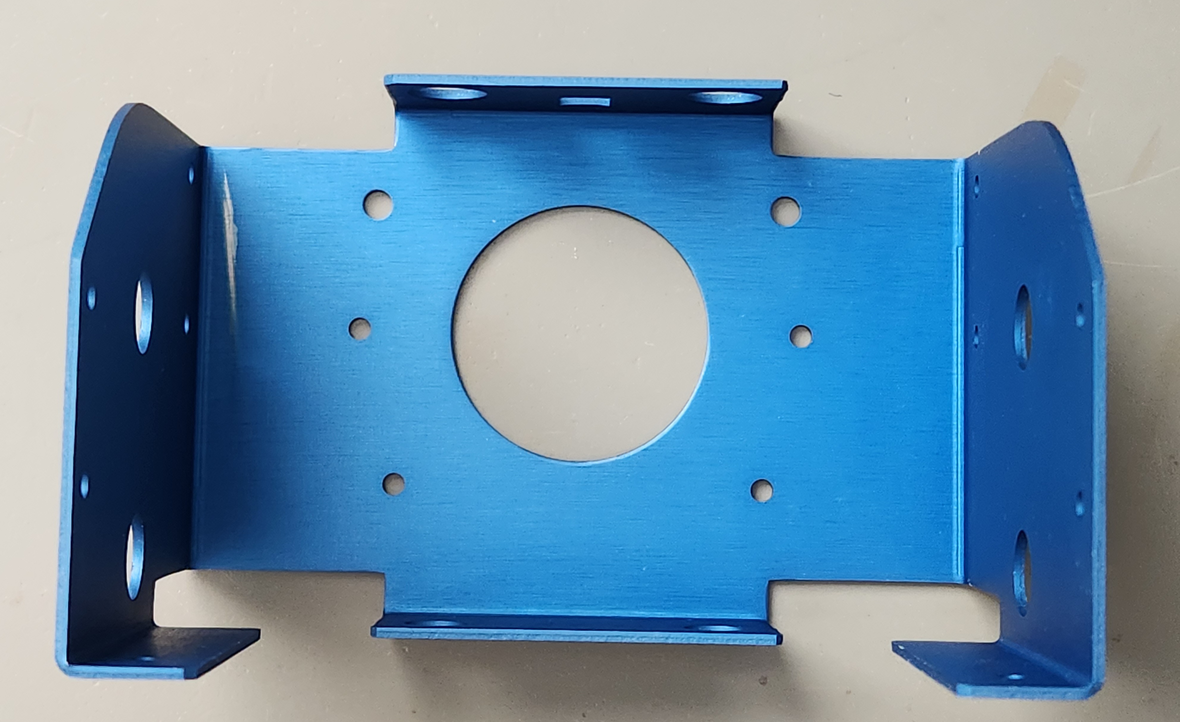
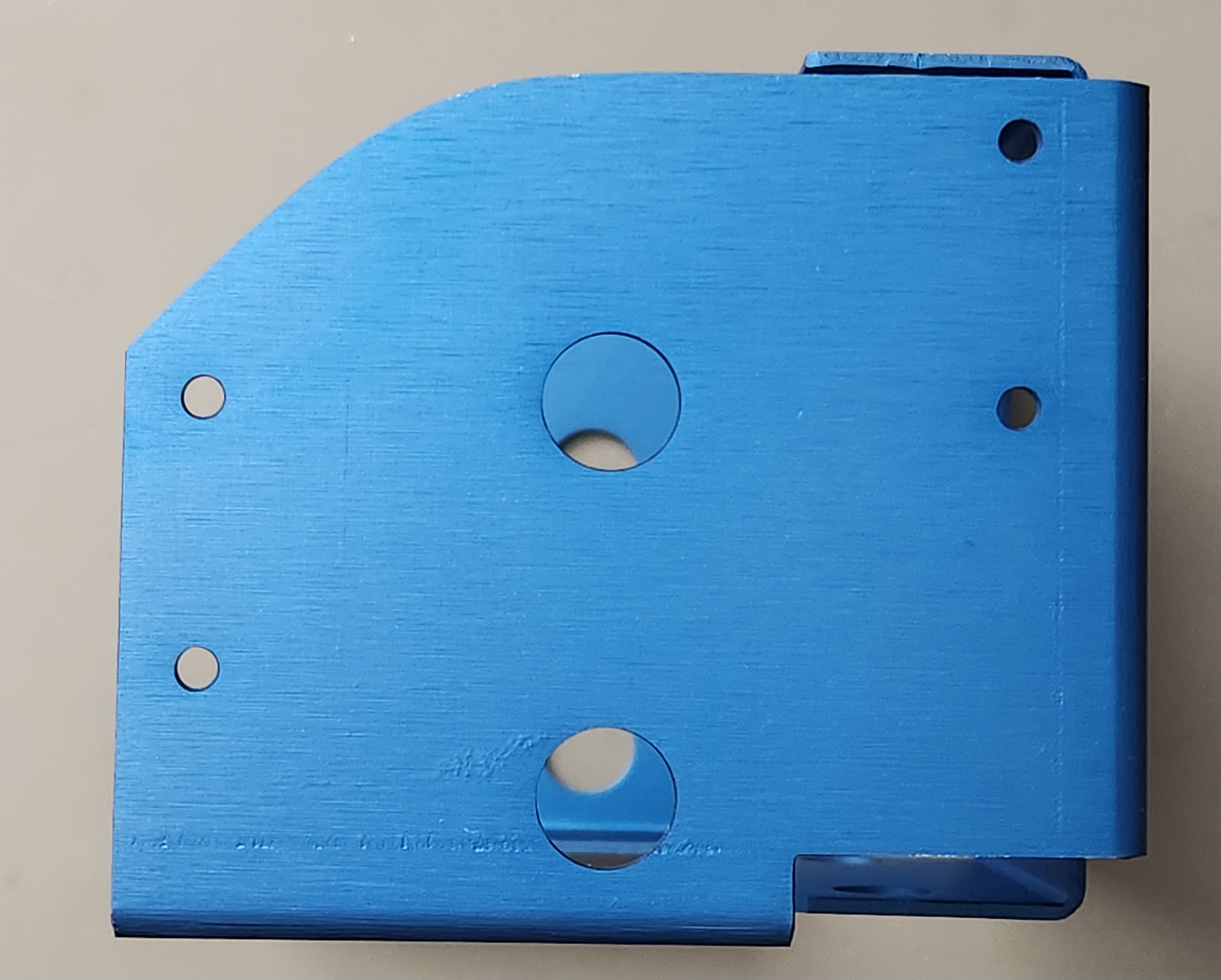
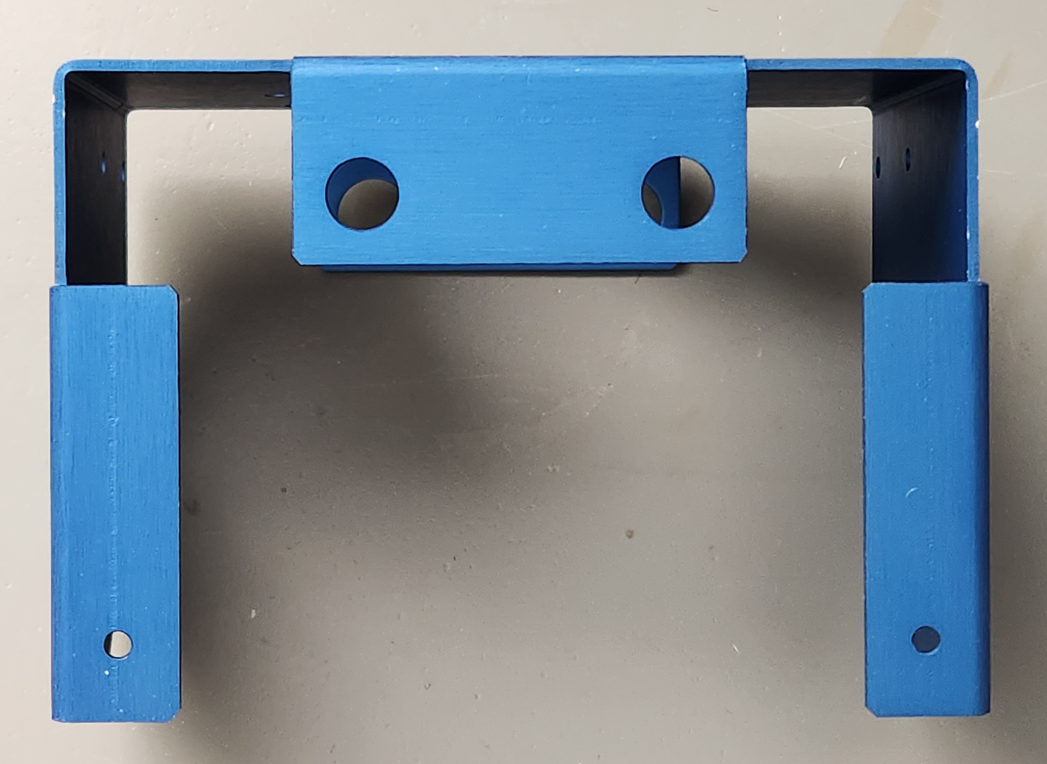
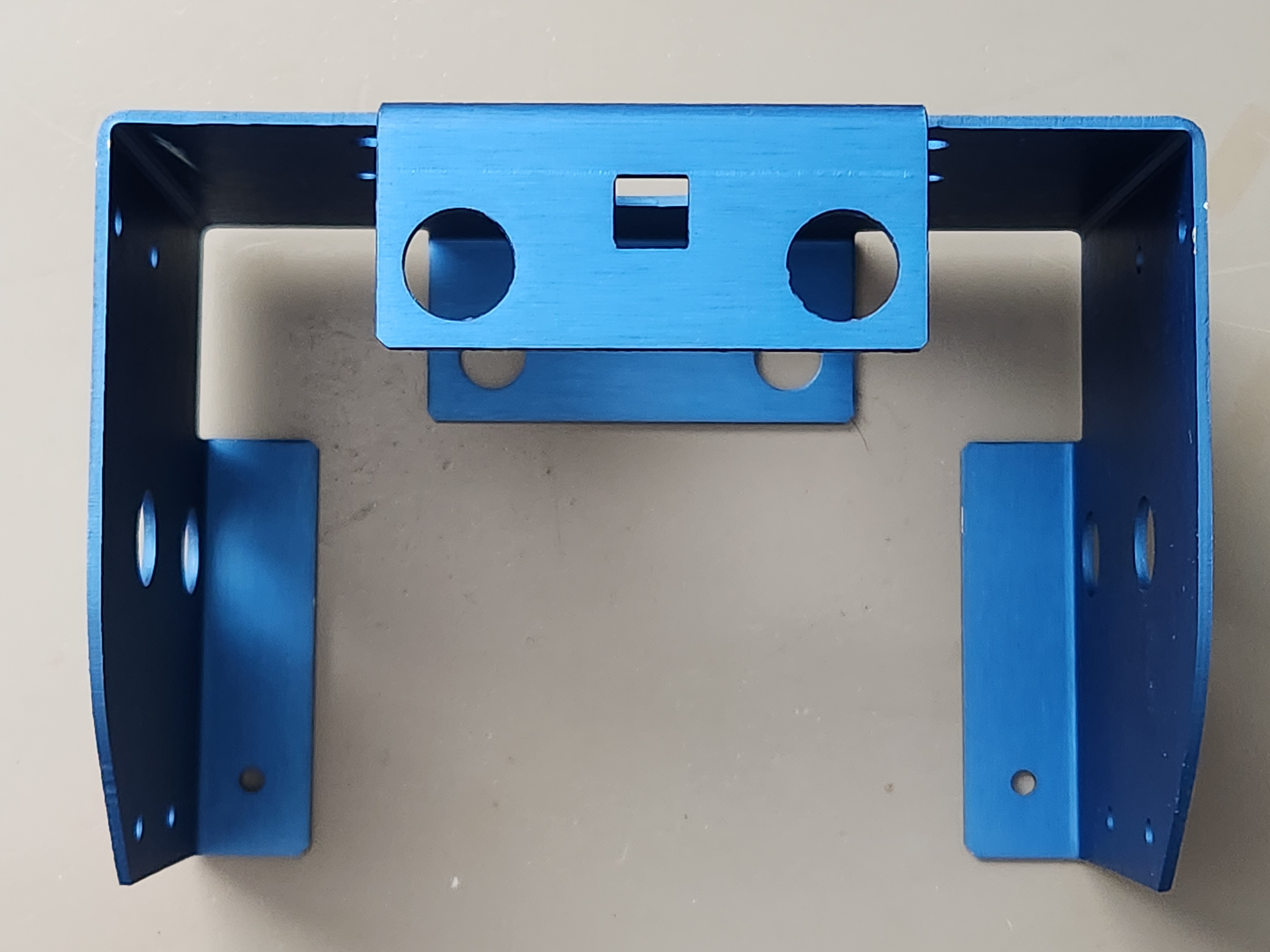
- 3 blue aluminium parts – pelvis, axle retainer, penslide
- 1 M4 captive nut to go in the square hole between the pillar tops – to hold on add-ons
- 2 tool clips for pen
- 2 grey plastic leafs with hole (see above)
- 2 black foam blocks (see above)
- 2 drive bosses
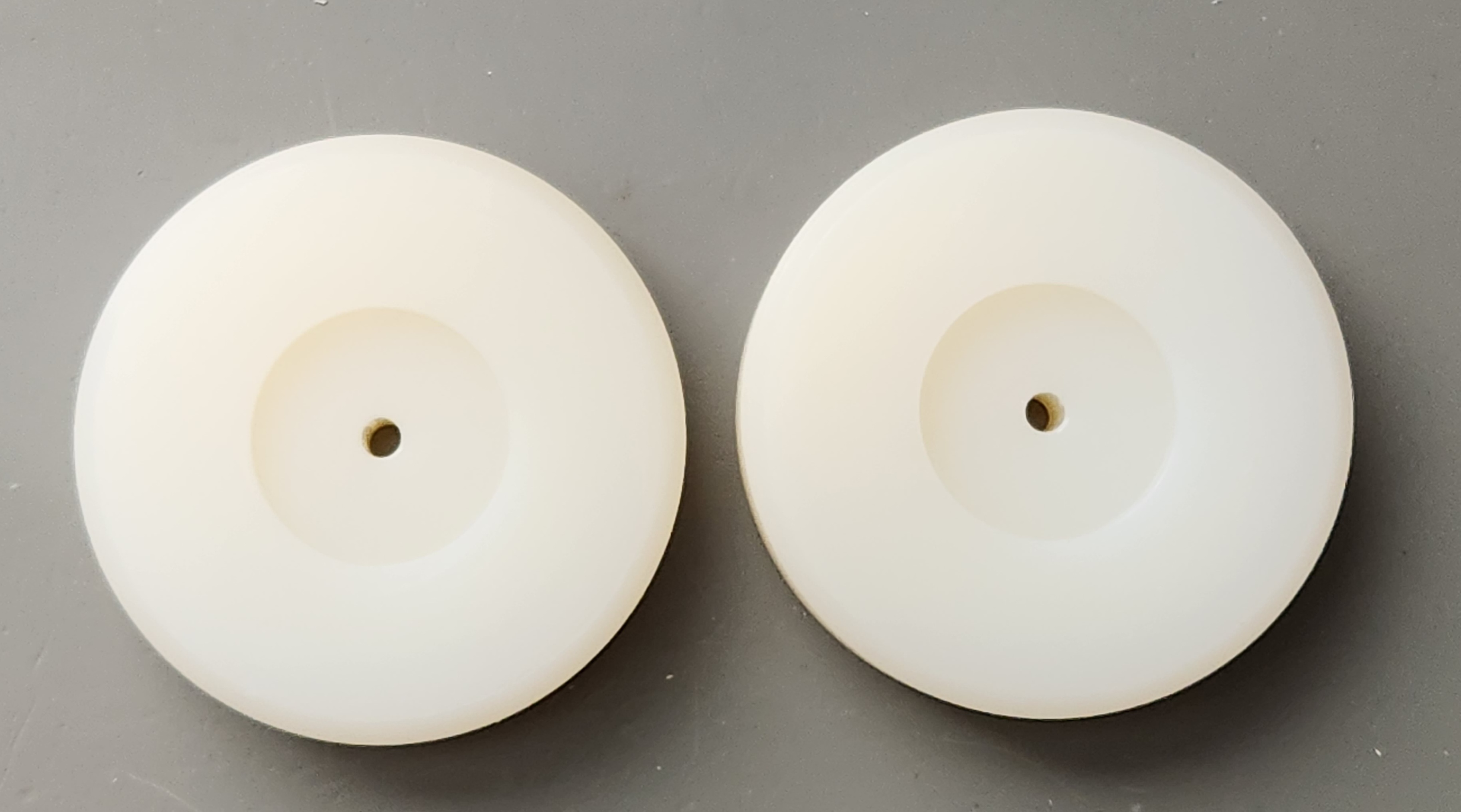
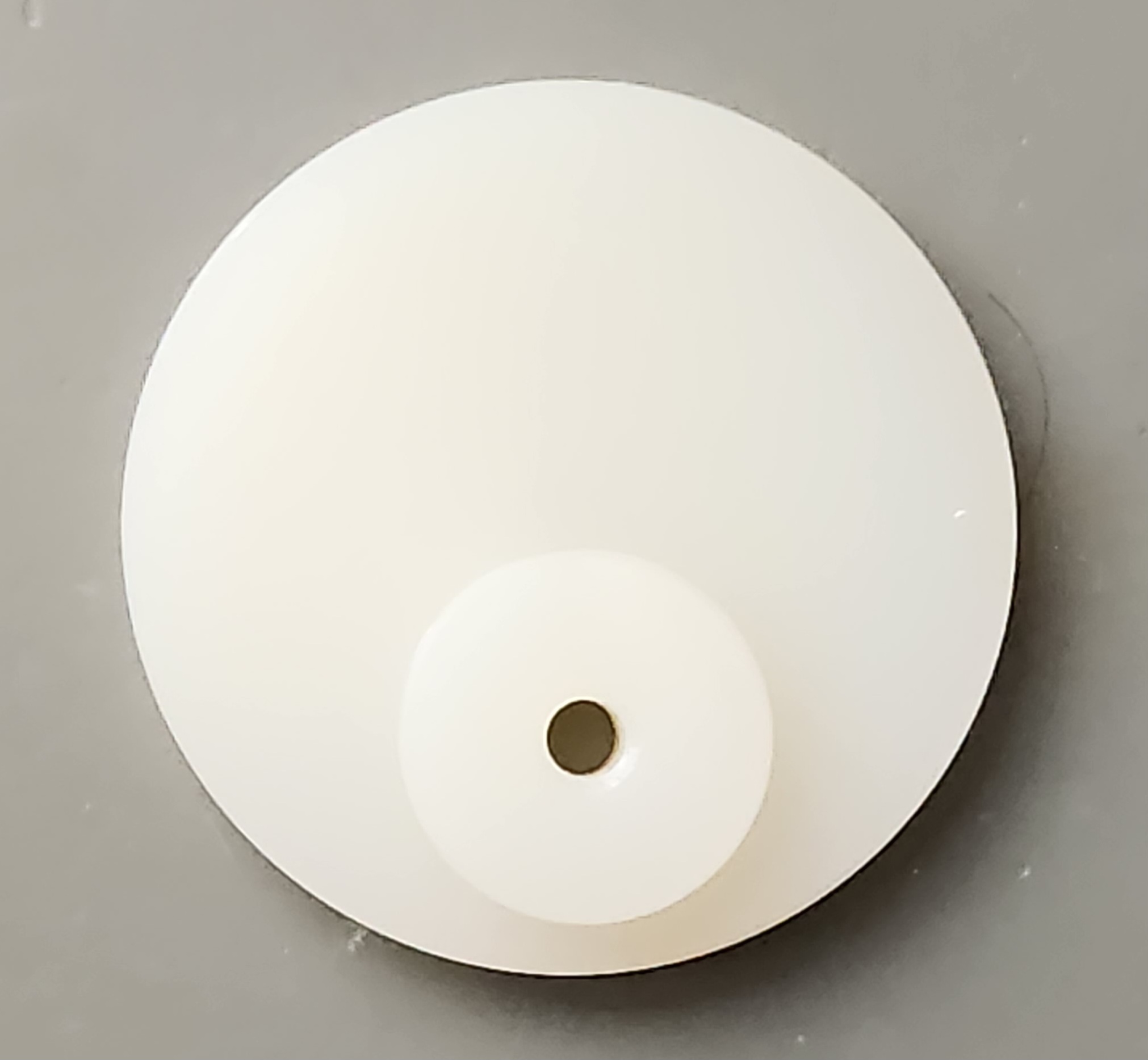
- 2 nylon wheels
- 2 rubber ‘O’ ring tyres
- 2 brass curved shim washers (between wheel and push-on speed-nut to take up play)
- 2 big clear plastic washers to go between the wheels and the pelvis
- 2 push-on speed-nuts to retain the wheels
- 1 axle
- 1 nylon pen cam
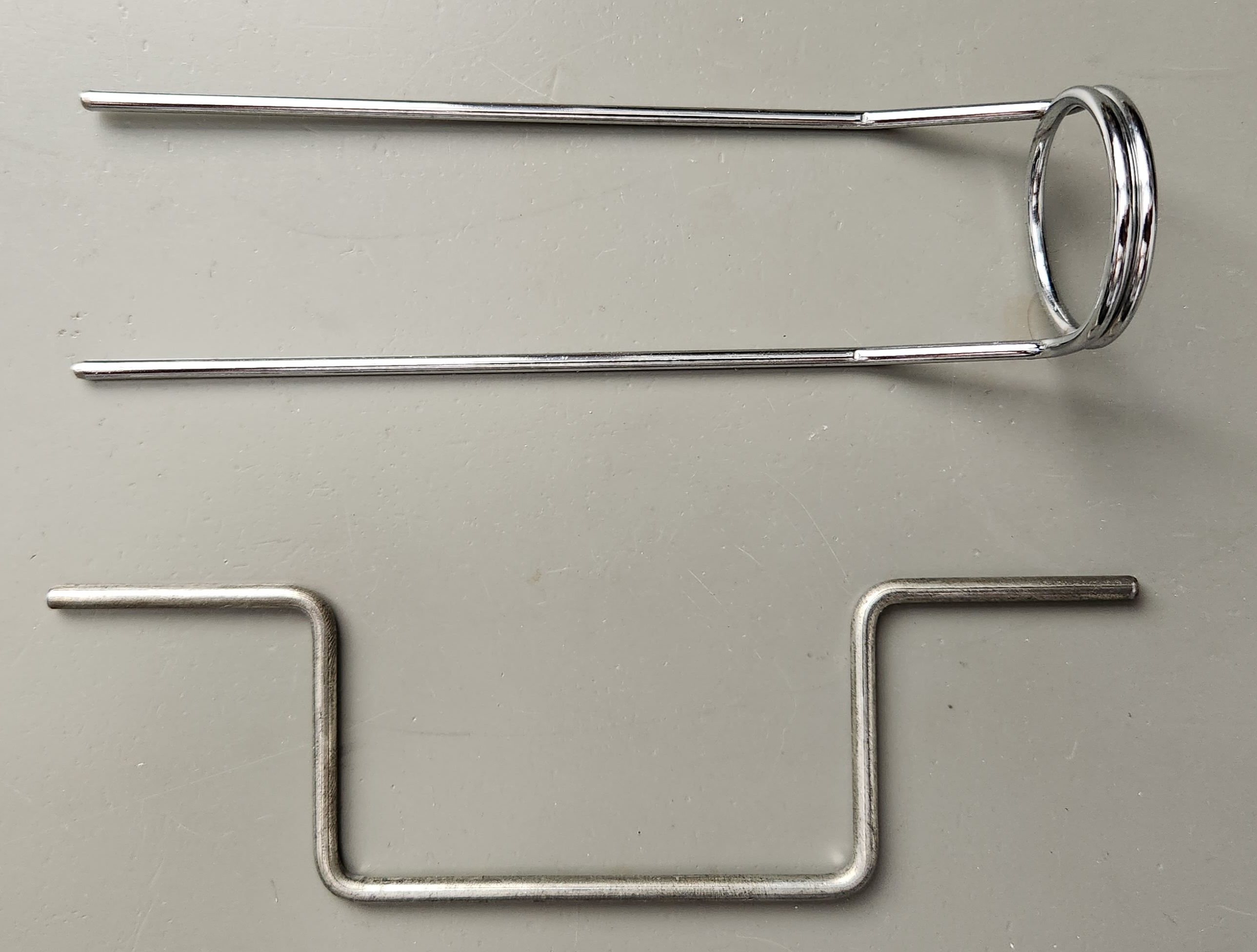
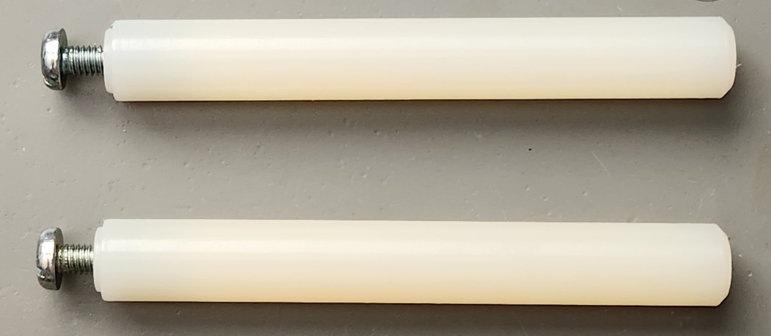
- 2 nylon slide pillars that hold the halo
- 1 halo cable support
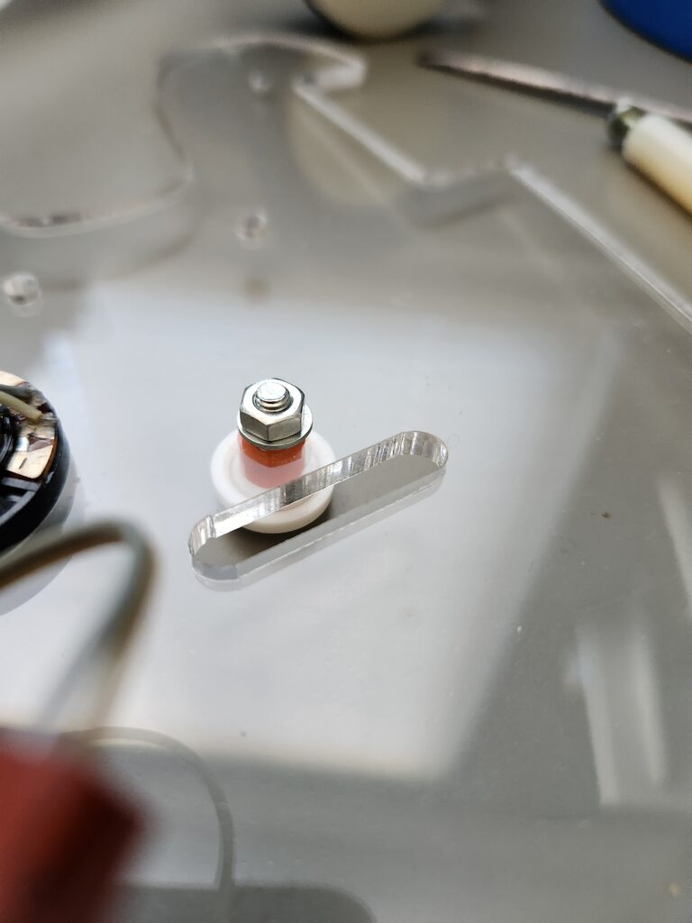
- toe parts – M4 csk screw, nut, spacer, washer, nylon toe base, nylon toe dome
- PCB mounts – 2 off M4 screw, nut, spacer, nylon washer
Here are some pictures of the mechanical assembly at various stages:
Sinclair QL Software (Transfer and Use)
Time to turn my attention to software. The main development for this robot was done by David for the Sinclair QL and he’s been kind enough to post the original software to his website. Unfortunately while these files are complete they are as ASCII text, BASIC programs/data and need to be transferred to the QL for storage on and running from microdrive or hard disk. Fortunately I was successful in this transfer.
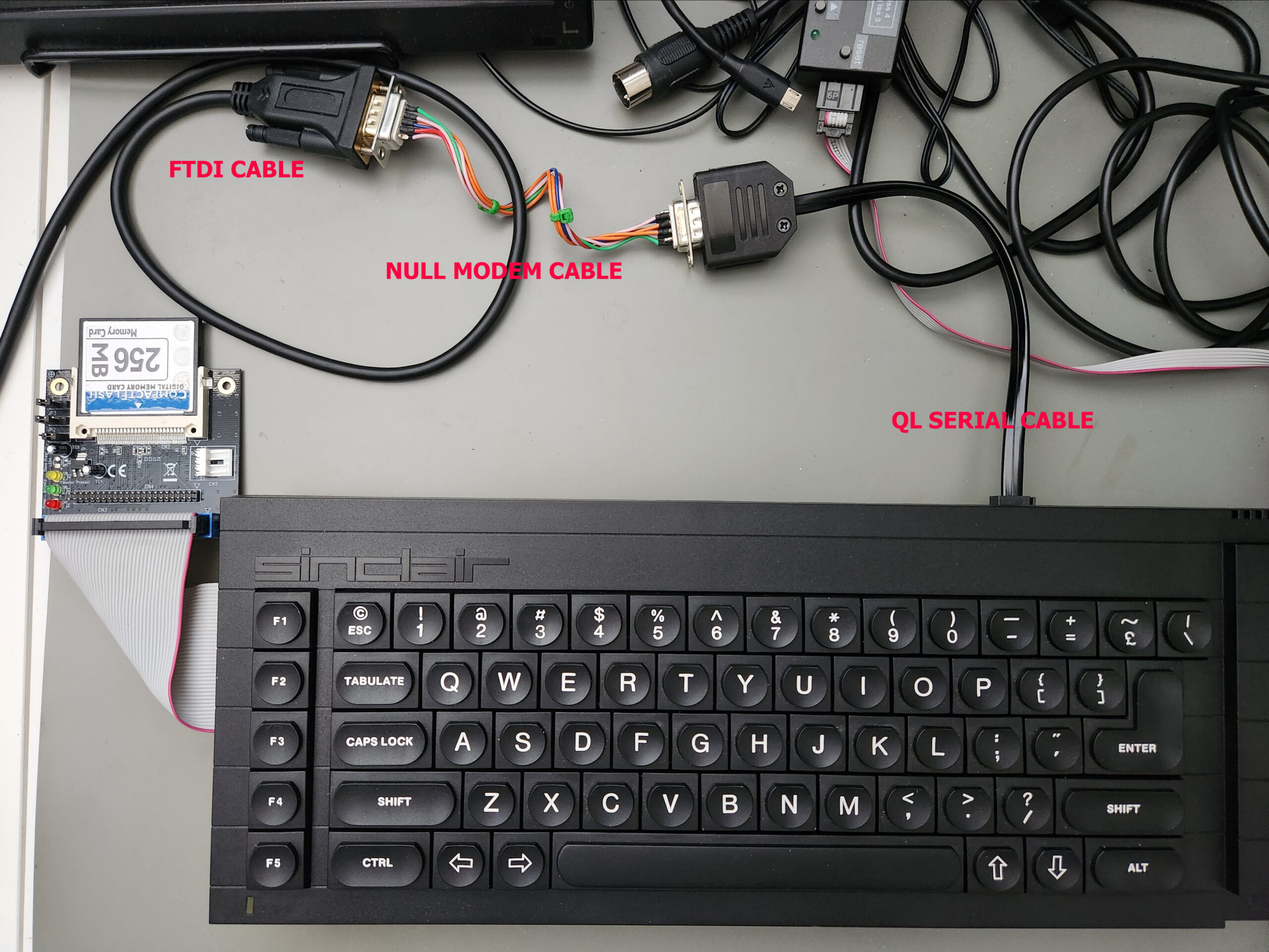
The first step is to connect your QL to a PC using a serial cable (adding a DE9-F to the unterminated end), null modem adapter and an RS232 interface (in my case an FTDI USB adapter). Once connected I fired up the QL and TeraTerm on my PC. Settings for TeraTerm should be COM4 (or whatever port the adapter appears on), 9600 baud, 8 data bits, no parity, 2 stop bits*, RTS/CTS flow control (assuming they are connected at the cable and null-modem adapter) and finally 1ms/char TX and RX delay. I often find I have to add a short delay when doing transfers to old equipment to avoid corruption, despite flow control being active (it remains a mystery). With these settings (and local echo on so you can see what’s happening) you can then use File–Send File to send the text file down to the QL (but don’t press ok just yet). Following some Youtube advice I selected Binary file type (despite these being text only).
*take care on this. With one stop bit set, things will generally work with an occasional error in the transferred data (see below)
With this done and ready to go you can then head over to the QL and type:
copy ser1hr to win1_zero2_basAs you can see I’m copying this to the win1 partition of a hard disk (actually the CF card you see above). I tried copying directly to mdv3_ (vDriveQL microdrive emulator) but the transfer seemed to be falling over part way through with a ‘media changed’ error. However copying to the hard disk first and then copying over to the microdrive from the hard disk was fine. I repeated this for the zero2_bas (main file), clone_bas (cloning file, not used), Zmem and Zmem_names (data) files – without these you’ll get errors.
Note you can easily check if the serial comms is working since…
copy ser1hr to con…copies data to the console (screen) output conveniently. You can exit either copy with CTRL+space (break) however please note that the transfer takes much longer than TeraTerm seems to indicate. I’m not sure if this is caused by delays emptying a buffer at the PC end or the QL end but (lesson learned) you need a long wait before breaking on a long program.
Fortunately you don’t need to do this since I have saved all of the required files to a .MDV file, which can be saved straight to an SD card and accessed with a vDriveQL connected.
Changes
Note that this is based on the ‘V2.8 for standard QL’ version but I have made some changes:
- Edited line 340 to change
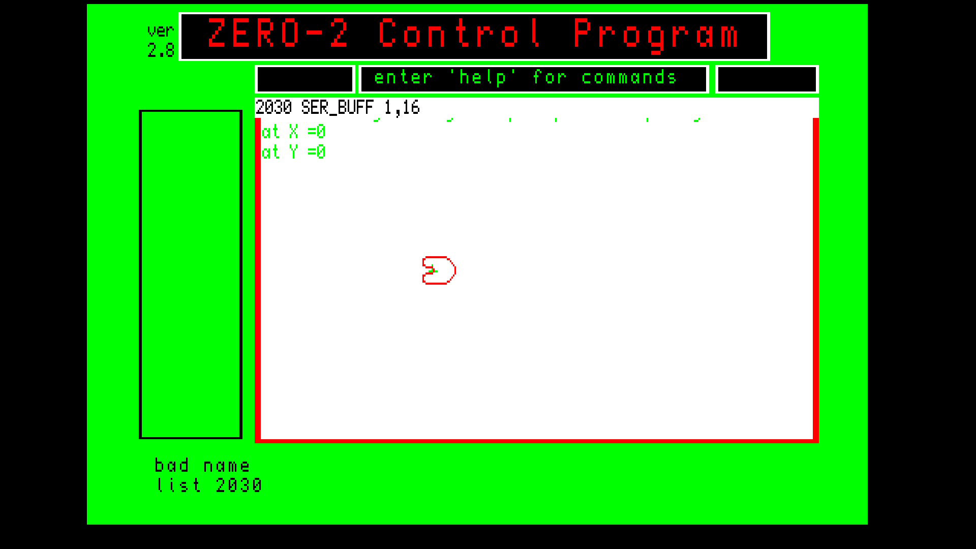
directory$to'mdv3_'(or change to wherever you are running the software from (needs to pick up the data files) - Edited line 2030, to
REMarkthis line out, sinceSER_BUFFis a SuperBasic extension with SMSQ/E that I don’t have (hopefully this won’t cause comms issues to Zero2, let’s see ! - Corrected lines 8710, 9310 and 11820 which suffered some corruption on transfer (pitfalls of transferring large files with no parity or error correction *and the wrong number of stop bits)
The program can be loaded load "mdv3_zero21_bas" and run directly (renamed to zero21_bas to differentiate from the as-published V2.8).
Initial Bring-up and Testing
Amazingly, on initial testing both the original board and the clone controller board are working well. There was a minor issue with a dry joint on the original board (connector to the pen motor) but for 40 year old electronics, one intermittent fault is not so bad ! The clone board also worked well, but in this case I chose to make some adjustments to the capacitors that set the tone of the horn. I changed C6 and C5 from 4n7 and 10n to 1 and 2n2 respectively. This is now closer in tone to the original but still a little lower (I think due to variances in the thresholds on the 40106 Schmitt trigger inverters). I did note that when setting the clock speed, I could not set this high enough until I switched positions of IC9 and IC10.
In terms of bring-up process, if you are building one of these I recommend testing the board out of the robot initially, fitting only IC10 for the first checks, applying power via the interface box and umbilical cord (with a current limited power supply: 9v, 200mA). Use a ‘scope on the CLK test point while adjusting R29 for the required 76.8KHz (+/- 5%) clock to support 4,800 baud communications. At the same time it’s worthwhile checking for a stable 9V (+/- 0.5V) on pin 9 of IC7 and IC8 and a stable 5V (+/- 0.2V) on pin 1 of IC1. With this done you can then turn off the power supply, fit the other ICs and re-power. Current consumption should remain below 200mA at this point.
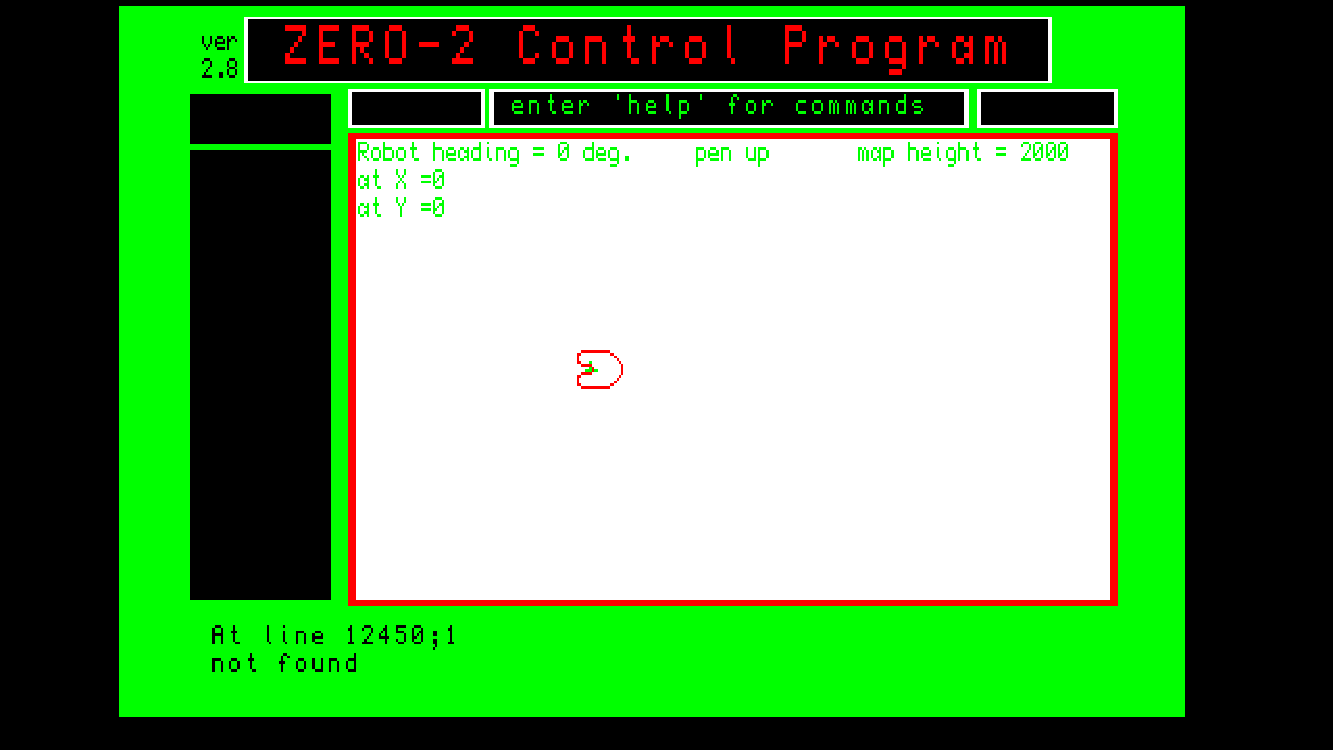
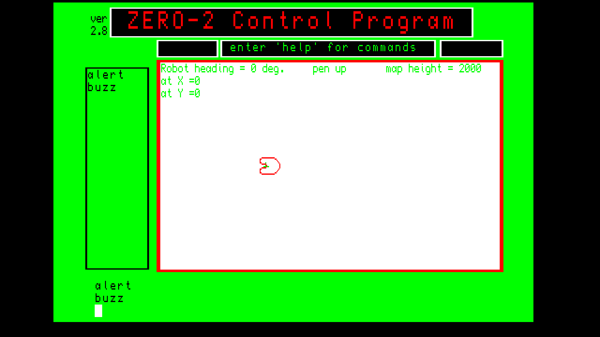
With all these preliminary tests done you can safety increase the power supply current limit to 800mA and connect the motors and speaker respectively. With the QL connected and running the Zero2 Control Program you can then check operations such as FD 100, RT 90, PU, PD (for the motors), FLSH 5 and HOOT 5 (lights and horn).
Here’s a small memorised program running on Zero2 with both the original and clone controller boards (for comparison):
As you can see this is without the body shell fitted (for easy access). It’s also worth noting that the body shell will require the connector hole enlarging a little to accommodate the RJ45 connector (taller than the BT-style connector of the original). Video is also available on YouTube in case the embedded video above breaks.
Finally to note, one thing that can’t be tested/used by the QL software right now is the line following sensors. I might try to modify the software to use these or alternatively write some special software once I have checked these are actually working.
More updates to come on the build, interface, and software for other computers…
To do (my notes):
– Create repo and add link
– Update schematic with tweaked component values
– Add details on the clone interface card and enclosure
– Update MDV archive (since more transfer errors found)